04581740 Edition 2 December 2007

Insight IC-D and IC-M DC Assembly Tool Controller
User Manual

Keep instruction data

Contents
| Section 1 - Introduction ...................................................................................................................................... 4 | |
|---|---|
| 1.1 Control Panel ................................................................................................................................................. ........................................................................................................................ | 4 |
| 1.1.1 Navigation Buttons | 4 |
| 1.1.2 Digital Keyboard .................................................................................................................... 1.1.3 Screen Configuration ..................................................................................................................... | 5 5 |
| 1.1.4 Screen Elements............................................................................................................................ | 6 |
| 1.1.5 Using Menus and Pages | Display..................................................................................... 7 |
| 1.2 System Options............................................................................................................................... | 7 |
| 1.2.1 Industrial Bus | ..................................................................................................................... 7 |
| 1.2.2 Additional Inputs/Outputs.................................................................................................... | 7 |
| 1.2.3 Mounting Bracket...................................................................................................................... | 7 |
| Section 2 - Installation | ..................................................................................................................................... 8 |
| 2.1 Assembly........................................................................................................................................................ | 8 |
| 2.2 Connection to power sources ........................................................................................................ | 9 |
| 10 | |
| 2.3 Connection of input/output peripheral devices....................................................................... | |
| 2.3.1 Input activation ........................................................................................................................... | 11 |
| 2.3.2 Output signal acquisition .................................................................................................... | 11 |
| 2.3.3 Assignment of default value to input/output.................................................................. | 12 |
| 2.3.4 PLC connection and communication setup ......................................................................... | 12 |
| 2.3.5 Configuration switch installation and setup...................................................................... | 12 |
| 2.3.6 Indicator block setup and connection | ....................................................................... 12 |
| 2.4 Connection of other peripheral devices.................................................................................... | 12 |
| 2.4.2 Setup and connection of bar code reading devices................................................. | 13 |
| 2.5 Connection of emergency stop button ...................................................................................... | 14 |
| 2.5.1 Single spindle mode.............................................................................................................. 2.5.2 Multi-spindle mode..................................................................................................... | 14 |
| 2.5.3 In the absence of an emergency stop button..................................................................... | 14 15 |
| 16 | |
| 2.6 Network connections | ....................................................................................................... 16 |
| 2.6.1 Ethernet connection .................................................................................................................. 2.6.2 Computer connection and setup through Ethernet port. | ................................................... 16 |
| 2.6.3 Industrial bus card connection. ............................................................................... ........................................................................................................... | 16 |
| 16 | |
| 2.7 Spindle head setup | 17 |
| 2.8 First startup.......................................................................................................................................... 2.8.1 Procedure | 17 |
| startup ....................................................................................................................... Chapter 3 - Controller IC-D Programming .................................................................................. | 18 |
| 3.1 Setup Menu (Settings).......................................................................................................................... | 18 |
| 3.2 Quick Setup (Quick Configuration) ........................................................................................................... 3.2.1 Language selection.................................................................................................................................. | 18 18 |
| 3.2.2 Programming in the Quick Setup menu ..................................................................................... 3.3 System Setup (System Settings)........................................................................................................ | 18 |
| 3.3.1 Passwords........................................................................................................................................... | 20 |
| 20 | |
| 3.3.2 Time and date setup........................................................................................................... 3.3.3 Operation number and controller network address (CAN).............................................................. | 21 |
| 3.3.4 Others | 21 21 |
| functions............................................................................................................................. 3.4 Spindle Setup (Spindle Settings)..................................................................................................... | 22 |
| 3.4.1 Physical | 22 |
| connection............................................................................................................. 3.4.2 Spindle Settings Page | 22 |
| ..................................................................................................... 3.4.3 Automatic Calibration Function | 24 |
| ......................................................................................... 3.5 Serial Setup (Serial Port Setup) ............................................................................. | 24 |
| 3.5.1 Protocol (Protocol) ....................................................................................................................... | 24 24 |
| 3.5.2 Baud Rate (Baud Rate)..................................................................................... 3.5.3 Parity (Parity) | 24 |
| ........................................................................................................... 3.5.4 Bits Per Character (Bits per Character) | 24 |
| ............................................................. 3.5.5 # of Stop Bits (Number of Stop Bits) ......................................................................................... | 24 |
| 3.5.6 Host Address (Host Address) ............................................................................... | 24 |
| 25 | |
| 3.6 Connection to PC.................................................................................................................................... 3.6.1 Ethernet Setup (Ethernet Settings)............................................................................................ | 25 |
| connection............................................................................................. | 25 |
| 3.6.2 Additional Parameters Data Transfer to USB Drive................................................................................................... | 25 |
| 3.7 | |
| 3.7.1 Installation....................................................................................................................................... | 25 |
04581740_ed2
| 3.7.2 Extraction.................................................................................................................................... | 26 |
|---|---|
| 3.8 PLUS Settings Menu................................................................................................................................. | 26 |
| Section 4 - IC-D System Management...................................................................................................... | 27 |
| 4.1 Introduction | .................................................................................................................................................. 27 |
| 4.2 Configuration Selection............................................................................................................................... | 27 |
| 4.3 Operation Monitoring................................................................................................................................. | 28 |
| 4.3.1 Torque and Angle of Tightening................................................................................................................. | 28 |
| 4.3.2 Status Color Indicators.............................................................................................................................. | 28 |
| 4.3.3 Group Operations............................................................................................................................ | 28 |
| 4.4 Message Area......................................................................................................................................................... | 29 |
| 4.5 Statistics and Service Signals................................................................................................................... | 29 |
| 4.5.1 Fault Statistics Signals........................................................................................................................... | 29 |
| 4.5.2 Service Signals.............................................................................................................................. | 29 |
| Section 5 - Quality Control................................................................................................................... | 30 |
| 5.1 Menu Statistics (Statistics) ............................................................................................................... | 30 |
| 5.1.1 Page Cycle Log ...................................................................................................................... | 30 |
| 5.1.2 Page Spindle Statistics (Spindle Statistics) .................................................................. | 33 |
| 5.1.3 Page Stats Settings (Stats Settings)............................................................................ | 33 |
| 5.1.4 Page Powerhead Stats........................................................................................................... | 34 |
| Section 6 - Diagnostics and Troubleshooting ....................................................................... | 36 |
| 6.1 Menu Diagnostics (Diagnostics) ............................................................................................................. | 36 |
| 6-1.1 Page System Test .................................................................................................................. | 36 |
| 6.1.2 Page Display Inputs (Display Inputs) ................................................................................. | 37 |
| 6.1.3 Set Outputs (Set Outputs) ....................................................................................................... | 37 |
| 6.1.4 Page Tool Test (Tool Test).............................................................................................. | 38 |
| 6.2 Event Log ..................................................................................................................... | 39 |
| Appendix 1 - Technical Specifications of the System and Spare Parts .................................................. | 40 |
| Technical Specifications of the Controller Insight ...................................................................................... | 40 |
| Pinout of Contacts.................................................................................................................................... | 40 |
| Default input/output assignments ....................................................................................... | 40 |
| Inputs ...................................................................................................................................................... | 40 |
| Outputs ................................................................................................................................................... | 41 |
| Recommended spare parts list........................................................................................................... | 41 |
| Outside.................................................................................................................................................. | 42 |
| Under the cover........................................................................................................................................... | 43 |
| Side....................................................................................................................................................... | 44 |
| Appendix 2 - Event codes .................................................................................................................. | 45 |
| Event code explanations ....................................................................................................................... | 45 |
| Event code table................................................................................................................................. | 45 |
04581740_ed2
Section 1 - Introduction
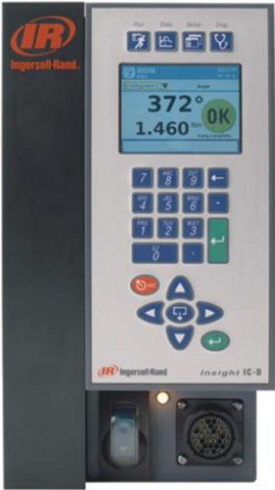
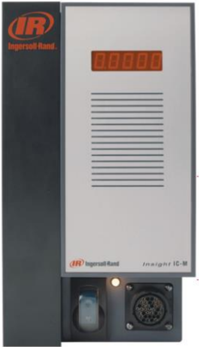
Insight IC-D and IC-M - programmable electronic controllers for managing spindles of Ingersoll Rand QE and QM series assembly tools, depending on model, to perform repetitive connection tightening operations. Programming is available for individual spindles held by the operator and for multiple spindles combined into a single unit (known as a spindle head) for manual or automatic tightening operations. This manual provides information only about Insight IC-D and IC-M controllers; spindles are accompanied by their own operation manuals. Although the IC-M performs the same functions as the IC-D, it does not have a display and keyboard, but is equipped with a single-line display. Many functions of both devices are programmed using a dedicated software. Programming instructions are provided in the PC manual. No access to internal components of the Insight controllers is required, therefore, no instructions on this matter are included in this section. This manual contains information on installation, setup, programming, operation, troubleshooting, and fault diagnosis of IC-D and IC-M controllers. The main elements of the IC-D controller are shown below in the figure.
1.1 Control Panel
Access to all display elements of the IC-D is achieved through four menu buttons on the front panel. Navigation between display pages and data entry are performed using navigation keys and a digital keypad.
Navigation Keys
The arrows on the navigation keys (see figure below) are used to move between screen elements (buttons, drop-down fields, etc.). When moving to any screen element, that element will be highlighted by a frame. Pressing the Enter button on the panel
Figure 1 - Main Panel
04581740_ed2
Navigation (or on the numeric keypad) activates the currently selected element. (The actual action is equivalent to clicking a screen button with a mouse).
Screen elements accompanied by an expansion icon can be expanded to view additional options. Pressing the expansion button located in the center of the navigation panel opens a specific element and displays its options. Use the arrow keys to navigate between options and press Enter to select an option. The exit key is used to cancel certain operations.
Numeric Keypad
When transitioning to a screen element requiring data input (an input field), use the numeric keypad to enter digits.
Most input fields require numeric data. Simply press the required digit directly on the keypad. If you make an error, press the space bar to delete the digit, or press ESC to return to the previous value. When the required digits are entered, press Enter to confirm the entered value.
Screen Configuration
The graphical display has two distinct areas, as shown below.
Figure 4 - Graphical Display
| Screen element | Description |
|---|---|
| Header line | The header line indicates the current Insight controller menu, date, and time. |
| Main window | All submenus, parameters, and input fields are displayed in the main window. |
0458174-ED2
Screen Elements
All pages displayed on the Insight IC-D screen have some common graphical elements. These graphical elements, known as screen elements, are shown below.
During current operations, use the navigation keypad keys to move the cursor between individual screen elements. A yellow border around a screen element indicates that the cursor is currently on that element.
Information Output Fields
Figure 5 - Screen Elements
| Screen element | Description | Icon |
|---|---|---|
| Button | To click a button, use navigation keys to select it and press the Enter key to confirm. A yellow border around a field indicates that it is selected. | |
| Dropdown list field | A dropdown list field is indicated by an expansion symbol. To open the list, use navigation keys to select it and press the expansion key. | |
| Input field | Use navigation keys to select the input field and enter a value using the numeric keypad. Press the Enter key to confirm. Pressing the ESC key before confirming with the Enter key restores the previous value. | |
| Toggle button / Switch button | Use navigation keys to select the toggle button or switch button. To switch between the 'on' and 'off' states, press the Enter key. | |
| Display information field | Display information fields contain data for viewing only or data that is editable. Use navigation keys to scroll data up/down and left/right. |
04581740-ED2
Menu and display screen navigation
- Press the appropriate button to select the menu you want to view. Four menu sets are available. The buttons for selecting these four menus are located above the display, at the top of the front panel of the display screen.
- To select a submenu of any menu, use the cursor (arrow). After selecting the desired submenu, press the Enter button. Any submenu can also be selected by pressing the number button associated with that menu. Each menu type has up to five submenu options.
- To enter numeric data into a field, select the required element on the screen and enter digits using the numeric keypad, then press the Enter button.
| Run (Execution) | Run screen displays tightening parameters (torque and angle after each operation). |
|---|---|
| Statistics (Statistics) | In the Statistics menu, raw data on tightening parameters and statistical analysis data are available. The Statistics menu contains four submenus. The first submenu, Cycle Log (Cycle Log), allows viewing previously saved data from previous cycles. The other submenus, Spindle Stats (Spindle Statistics), Powerhead Stats (Powerhead Statistics), and Stats Settings (Statistics Settings), contain general statistical parameters. |
| Setup (Setup) | The Setup menu is used for programming tightening strategies. Five submenus in the Setup menu have a Quick Setup (Quick Setup) function, allowing rapid programming of standard strategies, while the System Setup (System Setup) menu sets general parameters, such as date and time. The Setup menu manages key system parameters: in the Spindle Setup submenu, spindle parameters can be selected, and there are also Serial Setup (Serial Port Setup) and Ethernet Setup (Ethernet Setup), used for setting appropriate communication parameters. The PLUS Settings (PLUS Settings) submenu is available to customers using the PLUS data transmission protocol. |
| Diagnostics (Diagnostics) | In the Diagnostics menu (Diagnostics), programs for controller self-diagnosis of Insight are managed. Insight continuously searches for issues related to control or system components. The device issues warning messages about potential spindle or controller electronics problems and may also indicate the causes of malfunctions and suggest actions to resolve them. |
Optional system accessories
Industrial bus
Your system may be equipped with a network card for data transmission in an industrial network. This card enables the Insight controller to exchange data with other devices on the network. The device supports the following protocols:
- • Profibus
- • DeviceNet
- • MODBUS RTU
- • Interbus S
- • Ethernet IP/Modbus TCP
Additional inputs/outputs
The basic controller configuration includes eight discrete inputs and eight outputs for connecting peripheral devices. The Insight controller is equipped with an additional input/output module, providing an additional 16 inputs and 16 outputs, resulting in a total of 24 inputs and 24 outputs. Input/output functions are fully programmed in the ICS software.
Mounting bracket for in-wall installation
Insight standard delivery includes wall mounting brackets. As an option, a bracket for installing the controller in a cabinet is provided, allowing the controller to be mounted such that the radiator fins extend beyond the cabinet's rear wall. Using the bracket as a template, cut an opening in the cabinet's rear wall at the location where you plan to install the controller block. Install the cabinet-mounted bracket, first removing the wall mounting brackets from the controller block.
04581740_ed2
Section 2 - Installation
Installation
Installation
Ensure the mounted unit is stable, securely fastened, and properly aligned.
Power Supply Connection
04581740_ed2
2.2 Power Supply Connection
Ensure the main power switch is in the Off (off) position.
Insight controllers are available with various power cable options. In some cases, a single-ended power cable is supplied, requiring the user to provide the appropriate connector for connection. Refer to the power supply specifications marked on the Insight controller (on the right-side panel) and in the safety manual. Verify that your electrical circuit meets the power supply requirements of the Insight controller and the circuit breaker rating. Connect the AC cable to the appropriate plug.
The user is responsible for the installation of the Insight controller and wiring, which must be performed by a qualified electrician.
04581740_ed2
Connection of Input/Output Peripheral Devices
To remove the cover from the input/output block, loosen the mounting screw on the right-side panel, then press the tab under the screw and remove the cover.
Additional inputs/outputs (option)
04581740_ed2
Input activation
All incoming signals are powered by 24 V DC. The negative power supply must be connected to COM IN for each input group. It is recommended to use the internal power present on each input group and marked as 24VDC OUT +/- . Connect the 24VDC output to the required input signal (FORWARD, REVERSE, FREE SPEED, etc.).
To use the internal 24VDC power, a jumper must be installed between 24VDC OUT (-) and COM IN on each input group. To activate an input, a circuit must be closed between the required input and 24VDC OUT (+). The COM IN signal can be connected in daisy-chain to the next input group as shown in the input signal wiring diagram.
Obtaining output signal
All output signals operate from -24 V DC. The 24 V signal and its negative must be connected to the terminals marked as +/- 24VDC EXT on each output group. It is recommended to use external 24 V DC power. Output signals are returned from the corresponding output contact (ACCEPT, REJECT, HIGH TORQUE, etc.). See the output signal wiring diagram. You can connect +/- 24VDC in daisy-chain to the next output group.
04581740_ed2
2.3.3 Assigning default value to input/output
Default assignments are shown in the contact pinout on page 39.
2.3.4 PLC connection and communication setup
Note: All connections to the PLC, except for data collection lines, are made through the contact group. Data collection is performed via a serial industrial bus and/or Ethernet ports. For data collection, perform the connection setup procedure through a serial port or through an Ethernet port. The PLC connection to the contact group is described above.
Through the contact group, the PLC can send signals to the Insight controller and receive signals from it. It is important to use shielded cables for all signals from the PLC to the Insight controller; the shield should be grounded on the controller side. All inputs and outputs are activated/accepted similarly, as described above.
2.3.5 Configuration switch setup and configuration
- Connect the configuration switch to the Insight controller's contact group. The Config 1 wire should be connected to the input designated for executing Algorithm Config 1, and so on up to Config 8.
Note: Assignment of algorithms (or function assignment) to inputs and outputs is performed in the ICS program.
- Connect the spindle to the Insight controller and turn on the controller using the power switch on the front panel.
- Go to the Setup (Settings) menu, then to the Spindle Setup (Spindle Settings) submenu.
- If the configuration switch has more than eight positions, select External Binary (External Binary Signal) in the configuration selection dropdown list. If the configuration switch has eight or fewer positions, select External Discrete (External Discrete Signal) in the configuration selection dropdown list.
How to check the configuration switch
- After connecting and configuring the configuration switch, go to the Diagnostics (Diagnostics) menu, then to the Discrete Inputs (Discrete Inputs) submenu.
- When each position of the configuration switch is activated, a specific indicator should light up on the screen, showing changes in the configuration rows. (Note: When selecting External Binary in the configuration selection dropdown list under the Setup menu, Spindle Setup submenu, the first four configuration rows will indicate the binary-coded number of the selected configuration, 0000 indicates configuration 1 is selected).
2.3.6 Indicator Block Setup and Connection
- Find the wires of the appropriate color intended for connecting indicator blocks.
- Use the appropriate auxiliary cable to connect the indicator block to the controller's contact group located on the left-side panel of the Insight controller.
- Ensure the spindle is connected to the controller and turn it on using the power switch on the controller.
Under standard settings, colored indicators indicate the following:
2.4 Connection of Other Peripheral Devices
2.4.1 Printer Connection and Setup
Note: Insight supports communication with printers connected to the serial port for printing reports and labels with cycle execution parameters. (End of Run) data and labels. For printing data after operation completion:
- Connect the serial printer using a standard serial cable to the serial port on the left-side panel of the controller, marked I0I0I.
- In the Setup menu, under Serial Setup, select EOR Data Out (Data Output at End of Cycle) from the dropdown list.
04581740_ed2
- Verify that the data transmission rate in bps, parity control, number of bits per character, and number of stop bits match the settings of the serial printer. Adjust the settings if necessary.
- Turn on the printer and ensure it is operating correctly.
- Perform the tightening operation and verify that the operation result is printed.
For printing labels:
- Connect the serial printer using a standard serial cable to the serial port on the left-side panel of the controller, marked I0I0I.
- Via FTP, upload the Status.txt file to the controller's lbl folder. The Status.txt file contains information related to printer initialization and the application of specific settings.
- Via FTP, upload the Body.txt file to the controller's lbl folder. The Body.txt file is used exclusively to define the content and format of printed data.
- Reboot the controller.
- Turn on the printer and ensure it is operating correctly.
- Perform the tightening operation and verify that the label has been printed.
2.4.2 Setup and Connection of Barcode Reading Devices
Description
Thanks to ASCII barcode support, the Insight IC controller can be connected to any ASCII barcode scanner via a serial port or an Ethernet port. Each spindle can be equipped with its own scanner or, in the case of a spindle head, one scanner can serve the entire head. The barcode processing function operates in two primary modes: passive and active. The mode selection and other barcode processing settings are configured in the ICS software. More detailed information is provided in the ICS software manual.
Passive barcode processing mode
In this mode, barcodes are recorded for each cycle and stored in the cycle log, however, configuration selections are made without considering the barcodes.
Active barcode processing mode
In this mode, configuration selections are made based on the scanned barcodes. These data are also recorded for each cycle. Follow the instructions below to configure the controller for operation with a barcode scanner.
Barcode support
If the barcode support function is enabled for a specific spindle, regardless of where cycle data is sent (industrial bus, cycle log, printer output at the end of the cycle, or to the master device), scanned barcodes are sent along with these data. At startup, if a cycle begins before a barcode is scanned, the scan data is recorded as No Bcode (No Barcode). If a valid barcode is scanned and has the correct length, the scan data is recorded in all subsequent cycles until a new scan occurs. If an invalid barcode is scanned, the scan data records Invalid BC (Invalid Barcode).
Barcode compatibility with other functions
Gang Count (Group Counter)
The barcode function fully supports the Gang Count function. Scan data is recorded in all cycles within the group. If the ICS software setting Disable tool until scan is selected, the tool is disabled immediately after the group counter completes or after the entire assembly is finished (see Auto Increment (Configuration Switching)). To reset the group counter, activate the group reset input or press 0 (zero) and then Enter on the Run menu page. Re-scanning does not reset the group counter.
Auto Increment (Configuration Switching)
The configuration switching function is fully supported if the Disable tool until scan setting is selected. In any case, the barcode processing and configuration switching functions operate together. In active barcode processing mode, upon scanning a single
04581740_ed2
barcode, the configuration switching function becomes available for all configurations. The scanned barcode must be configured to select the first configuration in the configuration switching chain.
Spindle head
To work with the barcode for the spindle head, the spindle head must first be created. After creating the spindle head, set the barcode processing parameters for the first spindle in the spindle head. The scanned barcode is recorded only for the leading spindle, not for all spindles.
Emergency stop button connection
Using the emergency stop function, the spindle is immediately disconnected in case of an emergency (by the operator).
The emergency stop switch can be connected to the terminals at the bottom of the connection panel. The emergency stop switch for one device is powered by the internal 24 V controller power supply. If multiple controllers are installed in one cabinet and connected in a system, an external power source is required to power the emergency stop switch, so that the entire system is de-energized when the switch is pressed.
The emergency stop function is implemented using an emergency stop relay. The relay is energized under normal conditions. De-energizing the relay triggers an emergency stop. The relay has two outputs: 1 - 24 V DC, used by the motor control electronics (MCE) to control other relays that redirect the incoming alternating current to the rectifier on the spindle bus, and 2 - a voltage signal sent to the motor control board processor, signaling an emergency stop.
The relay coil terminals (+) and (-) are routed to jumper JP21 located behind the input/output panel cover. Power from the internal module power source is also supplied to jumper JP21. The relay is powered by 24 V DC, supplied to the coil terminals on jumper JP21. The 24 V DC power can come from an external power source or from the internal source.
Single spindle mode
When using the emergency stop function, jumper contact 2 (relay coil (-)) is connected to one terminal of a remote (normally-closed) single-pole switch with a mushroom-shaped button. The other terminal of this switch is connected back to jumper contact 4. Jumper contact 1 remains connected to contact 3 of the same jumper. In case of an emergency, the operator can hold the switch, interrupting the low-side circuit of the relay coil. The emergency stop function can also be implemented by connecting jumper contacts 1 and 3 to a remote switch. In this case, the high-side voltage of the relay coil will be interrupted (jumper contact 2 switches to contact 4).
Multiple spindle mode
When using the emergency stop button, each module's emergency stop relay is powered by an external 24 V source. In this case, pressing the mushroom-shaped button interrupts power supply to the emergency stop relays on all modules.
Note: Each relay coil requires a 25 mA power supply (nominal value).
04581740_ed2
In the absence of an emergency stop button
Even in the absence of an emergency stop button, the emergency stop relay must be powered to ensure normal system operation. For this, contact 1 on jumper JP21 must be connected to contact 3, and contact 2 to contact 4. This ensures that the relay is powered by the internal 24 V DC source on the module. The connection scheme does not depend on the number of spindles.
04581740_ed2
Network connection execution
Ethernet connection
Ethernet port is located on the controller Insight's connector panel. This port can also be used to connect a PC to the device to allow programming of parameters. If the device is connected to a PC, an Ethernet connection can also be programmed so that data is output after each tightening cycle.
Access the Setup menu, then the Ethernet Setup submenu. On the opened page, you can check IP address, subnet mask, and gateway settings. Here you can also enable or disable the Host Dynamic Configuration Protocol (DHCP). Enabling this protocol allows the network server to assign an IP address to the device.
Computer connection and configuration via Ethernet port
Computer connection and configuration via Ethernet port
Note: To connect a computer to the Insight controller, the ICS software is required.
- Connect the controller to the computer using a crossover Ethernet cable.
- In the Setup menu, under Ethernet Setup, check IP address, subnet mask, and gateway settings.
- If changes are required, press the Enter key on the Settings tab to access the Ethernet settings page, then make the necessary adjustments.
Note: To activate new Ethernet settings, the system must be restarted.
Industrial bus card connection
If the Insight controller is equipped with an optional additional industrial bus card, it can be connected to an industrial bus. Determine which industrial bus card is installed in your system, if any.
If the card supports the DeviceNet protocol, use the following table for proper connection of terminals:
| Plug connector | Screw clamp | Description |
|---|---|---|
| 1 | 1 | V- |
| 2 | 2 | CAN_L |
| 3 | 3 | SHIELD |
| 4 | 4 | CAN_H |
| 5 | 5 | V+ |
For any other industrial bus protocol, simply insert the appropriate terminal into the Insight controller.
Spindle head setup
Insight controllers synchronized with each other, controlling the tightening of a set of bolts, are referred to as a spindle head. When combining controllers into a spindle head, a daisy-chain connection must be made to establish a spindle head synchronization bus. Up to 40 Insight controllers can be connected. For each controller, two rotary address switches must be set according to its position in the chain.
- The upper rotary switch on the first controller of the spindle head must be set to position 0, and the lower one to position 1.
- Connect the synchronization cable to the lower connector of the first controller's spindle head.
- Connect the other end of this cable to the upper connector of the second controller in the head.
- On the second controller, set the upper rotary switch to position 0 and the lower one to position -2.
- Proceed in the same manner to connect the remaining controllers (up to 40 devices).
Note: The upper rotary switch is set to position 1 for devices 10–19, position 2 for devices 20–29, position 3 for devices 30–39, and position 4 for device 40.
- Set the contact group of the first and last devices in the chain as follows: 1 (on) and 2 (off), as shown below.
04581740_ed2
Note: All other devices in the spindle head must be set as follows: 1 (off) and 2 (off).
2.8 First Startup
Before the first startup of an Insight controller, a checklist must be performed. If any item on this checklist raises doubts, contact an Ingersoll Rand representative.
- • The controller housing is securely mounted in a vertical position and properly aligned.
- • Check the spindle connection and ensure the cable connector is firmly secured.
- • If external devices (printers, computers, etc.) are to be connected to the Insight controller, ensure they are connected to the corresponding ports on the panel (located on the left).
- • The power cable must be connected to an electrical network with the appropriate parameters.
2.8.1 Startup procedure
Once the check against the checklist is complete, power the Insight assembly system on.
- Turn the controller's disconnect switch to the Off (off) position.
- Verify the power network parameters to which the device is connected: 120 V, 16 A or 230 V, 8 A; 50–60 Hz.
- Ensure that the ground fault protection device (GFI (A)) is turned on (upper position).
- • Move the disconnect switch (B) up to the On (on) position. This switch supplies power to the graphic display, internal motor control electronics, keyboard, spindle(s), or spindle head.
- Approximately 130 seconds after, the Run (Execution) menu page will appear on the graphic display, indicating that the startup was successful and the controller is ready to operate.
- • To turn the entire Insight system on and off, use the disconnect switch.
- • A time interval is required between power disconnection and reconnection, at least five seconds.
04581740_ed2
Section 3 - Controller IC-D Programming
3.1 Setup Menu (Settings)
Programming of tightening strategies and input of numerous important system parameters takes place in the Setup menu and its submenus. The main tightening strategies are set in the Setup menu. In addition to strategies, this menu allows setting of basic system parameters, such as time, display language, units of measurement, and data transmission protocols. The Setup menu also allows setting a password for software and data access control. The following five submenus are part of the Setup menu:
- Quick Setup (Quick Setup)
- System Setup (System Setup)
- Spindle Setup (Spindle Setup)
- Serial Setup (Serial Setup)
- Ethernet Setup (Ethernet Setup)
- PLUS Setup (PLUS Setup) (for PLUS data transmission protocol users). The following subsections provide a detailed description of each submenu.
Quick Setup
Select Language
The first step when programming the Insight controller for operation is to select the display language. The language selection is performed in the System Setup submenu under the Setup menu. Language (Language) is the eighth parameter in the list on this page. Press the expand button and select the required language. The default language is English.
Programming in the Quick Setup menu
This menu is used for quick controller setup. Here, you can set parameters for one-step tightening strategies with moment or angle control. Only basic parameters are displayed on the screen. More complex, multi-step, and other strategies, such as moment control at the yield point or moment control during gripping, are programmed in the ICS program. Only the first eight configurations can be viewed and
04581740_ed2
programmed directly on the controller. The ICS program allows up to 256 configurations to be configured.
In the Quick Setup window, you can set key parameters of the selected tightening strategy. You can pre-program up to eight different tightening operations. These are called configurations. Different parameters may be displayed on the screen, depending on the selected tightening strategy.
For editing parameters in the Quick Setup submenu:
- Select the Setup (Settings) menu, then press Enter to select the first sub-menu Quick Setup (Quick Setup).
- Use the arrow keys to navigate to one of the eight configuration lines presented, numbered 1 through 8.
- Press Enter to proceed to step 2, the first page of the configuration settings setup.
- Navigate to the Strategy (Strategy) parameter and select either Torque Control (Torque Control) or Angle Control (Angle Control).
- Select the direction CW (Clockwise) or CCW (Counterclockwise).
- Navigate to the next parameter and select the torque unit: Nm (Nm), Ftlbs (ft-lbs), In-lbs (in-lbs), Kg-m (kg-m), or dN (dN).
- Use the right arrow key to select the required unit and press Enter to proceed to the second page of the configuration settings setup.
- Using the numeric keypad, enter the control values in either the Torque Target (Torque Target) or Angle Target (Angle Target) field, depending on which of the two strategies you selected for this configuration.
- The controller system automatically calculates and assigns values to all other parameters related to torque or angle control within the specified control values. If you need to modify these values, navigate to the corresponding input field and enter new values using the numeric keypad. Configuration settings parameters:
- If the assembly operation requires sequential tightening of a large number of bolts, enter the corresponding number in the Gang Count (Gang Count) field. For more details about the gang count, see below.
| Upper torque limit | Maximum allowable torque value during tightening. |
|---|---|
| Lower torque limit | Minimum allowable torque value during tightening. |
| Upper angle limit | Maximum allowable rotation angle of the fastener element. |
| Lower angle limit | Minimum allowable rotation angle of the fastener element. |
| Torque threshold | Tightening torque required for final seating of connection components; also the initial torque from which the angle measurement starts. |
| Free rotation | Maximum spindle speed during tightening (%). |
| Speed reduction point | Point at which the spindle switches to reduced speed for more accurate achievement of the specified torque. |
| Reduced speed | Spindle speed at % during rotation phase at reduced speed. |
04581740_ed2
- Use the Auto Increment (Auto Configuration Switching) parameter to enable the Insight controller to automatically switch between different configurations. Enter the configuration number that the controller should use after completing the current configuration. For more details about automatic configuration switching, see below.
- Set the Increment Reset (Increment Reset) parameter to specify the configuration the controller should use after receiving a reset signal.
- After entering all required configuration parameters, move the cursor to the Save (Save) button and press Enter to save the settings.
Gang Count (Gang Count)
某些装配操作涉及按顺序拧紧一定数量的螺栓(以下称为组)。例如,如果需要进行四颗螺栓的装配,请将Gang Count设置为4。控制器将跟踪每个螺栓的拧紧情况,并在完成时在显示屏上显示消息'Gang Complete'(组完成)。
If the group is successfully completed, in addition to this message, the controller sends a group completion signal to the spindle's input/output block. There are two methods to reset the group counter.
Use the mushroom-shaped button designated for this purpose on the group reset signal input.
On the Run (Execution) main screen, press 0 (zero) and then Enter to reset the group counter for this spindle.
Auto Increment (Configuration Auto-Change)
Configuration Auto-Change allows the controller to execute a sequence of specified tightening configurations. For example, if you have programmed six different configurations 1–6, you can set a tightening sequence such as 1–4–6 and 2–3–5. This parameter instructs the controller to which configuration to transition, enabling the system to perform operations with all programmed settings in Auto-Change mode. The Increment Reset (Auto-Change after Reset) parameter instructs the controller to which configuration to transition after activation of the configuration reset input signal.
Note: Before selecting the next configuration in the sequence, the current configuration must be successfully completed and the spindle starter must be released.
Startup Mode and Configuration Selection
The last two steps in the quick setup procedure are performed in the Spindle Setup (Spindle Setup) menu, where the startup mode and configuration must be selected prior to operation. Information on setting these parameters can be found in the Spindle Setup menu section on page 23.
3.3 System Setup (System Setup)
3.3.1 Passwords
The Insight IC-D controller is initially unlocked and provides full read and write access to all data upon first loading. This means that the system is not password-protected upon initial loading. The default password is 1111.
To assign a password:
- Navigate to the Setup menu, under the System Setup submenu, use the arrow keys to scroll down to the Password Logout (Password Logout) button.
- To exit the system, press Enter.
- Go back to the System Setup submenu and you will see that the 'Password Logout' button has been changed to 'Password Login (Password Login).'
- Press Enter to log in.
- Enter the default password 1111 in the pop-up window.
- To set a new password, go to the 'Change Password' page and press Enter.
- Enter your current password in the appearing window and press Enter.
- Enter your new four-digit password twice in the corresponding input fields.
- Press Enter to confirm the password change.
- In the System Setup submenu, go to the Password Timer (Password Input Timer) parameter to change the time period after which system access will be blocked by password. Available wait times: 30 s, 1 min, 2 min, 5 min, 15 min, and 1 hour.
04581740_ed2
Note: After each controller reboot, a password must be entered, even if the password timer has not expired. This does not apply to controllers with the password input timer disabled.
3.3.2 Setting Time and Date
Time and date settings are located in the System Setup submenu, including: Time Set (Time Setting), Time Mode (Time Mode), Date Set (Date Setting), Time Zone (Time Zone), and Date Format (Date Format). Time is displayed in 24-hour format.
To set date and time parameters:
- Enter the System Setup menu and go to the Time Mode parameter.
- Select Manual (Manual) or Auto (Automatic) (NTP). NTP = Network Time Protocol
Note: When selecting the Auto (NTP) mode, the Insight controller synchronizes its time settings with the Ethernet network during reboot. The Time Set parameter will be unavailable if NTP is selected.
- Upon selecting Manual mode in Time Mode, navigate to the Time Set parameter and enter the time for your time zone, then proceed to step 5.
- If Auto (NTP) mode is selected, navigate to the Time Zone parameter and select the appropriate time zone GMT (Greenwich Mean Time).
- Navigate to the Date Format parameter and select either MM/DD/YY (MM/DD/YY) or DD/MM/-YY (DD/MM/YY).
- At the end, navigate to the Date Set parameter and enter the date in the previously selected format.
Operation Number and Controller CAN Address
Job Number (Operation Number) and CAN Address (Controller Network Address) are located at the top of the System Setup (System Settings) page and are used to assign a unique number (ID) to each individual Insight controller. The ID serves as a unique identifier for each device in the network.
The Operation Number consists of four digits indicating the position on the assembly line. Each standalone Insight controller has its own unique Operation Number. However, controllers combined into a spindle head share the same number.
The CAN Address reflects what was mechanically set by the device's address toggle switches. It must always be zero when operating with a single spindle. If the address is not zero, mechanically adjust the address toggle switches on the device until they are set to zero. The System Setup page does not allow setting the CAN Address. When operating with a spindle head, the CAN Address must reflect the controller's position within the spindle head. For more information on configuring the CAN Address using the device's toggle switches, refer to section 2.7 "Spindle Head Settings."
3.3.4 Other Functions
In the System Setup menu, two additional functions are available. The first function contains two buttons to adjust the display contrast either upwards or downwards. The second function allows viewing the version numbers of various software components.
Contrast
To increase contrast, select the upper button and press Enter. To decrease contrast, select the lower button and press Enter. Increase Contrast
Decrease Contrast
Software Version Numbers
- Move the cursor to the right arrow button in the System Setup menu and press Enter to proceed to step 2.
0458174-ED2
- Press Enter to return to step 1 of the System Setup page.
Spindle Setup (Spindle Settings)
3.4.1 Physical Connection
Connect the Ingersoll Rand QE- or QM (or spindle heads) to the Insight controller from the front. Each spindle cable has a multi-pin connector with a rotary lock. Connect the spindle to the connector and secure it.
If the spindle is not present when the controller power is turned on, power is not supplied to the empty connector. This is a safety measure. The controller interprets the absence of a spindle as a spindle with a possible ground fault and does not supply power to it. To connect the spindle later, switch the main power switch to Off (off). Then connect the spindle, wait for five seconds, and turn on the power.
Note: It is prohibited to connect the spindle if the Insight controller is powered (power switch in the ON (on) position).
Spindle Settings Page
Note that the model number of the connected spindle is displayed on the Spindle Setup page under the heading. On this page, you can configure the spindle according to ten different parameters. Two buttons are also available here to restore factory settings for Transducer Range (Sensor Range) and Angle Constant (Angle Constant).
In the first parameter, Transducer Range (TR), where the sensor range is set, you can enter the required value in Nm for calibrating the output signal of the connected spindle's torque.
The second parameter is Angle Constant (Angle Constant). This parameter sets the value for calibrating the output signal of the spindle's angle.
Config Selection (Configuration Selection) - a parameter that defines the configuration selection mode. In the dropdown list, the following options are available: Internal (Existing), External Discrete (External Discrete Signal), External Binary (External Binary Signal), and External Ethernet.
04581740_ed2
(External Ethernet Signal). These options relate to configurations programmed in the Quick Setup (Quick Setup) menu or in the ICS program. If you use 24 configurations or fewer and select them by sending input signals to the controller, choose External Discrete. If you use more than 24 configurations, select External Binary. When choosing Internal, a dropdown list appears on the Run (Execution) page. In this dropdown list, you can select any programmed configuration for the connected spindle. If configuration selection is made through an external network device (PLC), select External Ethernet.
Fourth parameter in Spindle Setup menu - Spindle Operation (Spindle Control). Here, the method of sending start signal to the spindle is selected. You can also change the Insight controller control mode from manual (spindle starter) to automated (or stationary). A stationary spindle (or automated spindle) is a spindle that receives an external start signal remotely via the input/output connector located on the left panel of the controller. To switch from a manual to an automated spindle, select the Machine Mount mode in the dropdown list in the Spindle Operation window. To return to manual mode, select the Handheld Spindle mode in the same list.
Fifth parameter in Spindle Setup menu - Start Mode (Start Mode). This parameter is active only in Machine Mount mode. In automated control mode, this parameter defines the type of signal used for spindle start.
- • When Throttle (Constant) is selected, the start signal is similar to the signal sent in manual tightening mode when the operator holds the spindle starter button pressed continuously. In other words, the signal must remain active throughout the entire tightening cycle.
- • Pulse (Pulse signal) sets a single external spindle start signal, and the spindle continues to operate until the preset time expires or until the required tightening moment or angle is reached.
- • Dual (Dual signal) requires closing two relays — rotation speed and safety latch. This applies to spindles where the operator must activate both relays for two seconds to ensure a safe distance between their hands and the equipment. If no voltage is applied to either of the two inputs within these two seconds, the spindle stops operating.
The following two parameters — Tube Nut (Reverse) and Tool Switch (Tool Switch) — are used together to set the operation mode of manual spindles. The switch is located in the final instant position of the spring ring reverse mechanism. It remains active only when the operator holds it in that position. When released, the switch returns to the forward rotation position or the initial position due to spring action. For programming a connected manual spindle:
- Change Tube Nut Disable (Disable Reverse) to Enable (Enable).
- Set the Tool Switch parameter to Disable (Disable), Tube Nut 1 (Reverse 1), Tube Nut 2 (Reverse 2), Gang Advance (Group Advance), Gang Reset (Group Reset), Config Reset (Configuration Reset), or Tube Nut 3 (Reverse 3).
If the Tool Switch is set to Disable and Tube Nut is set to Enable, then switching the switch to reverse will be interpreted as usual, resulting in reverse rotation of the tool holder. When the switch is moved to reverse and the start button is pressed, the spindle will rotate in reverse until the tool holder returns to the open position. In this configuration, the instant position of the reverse switch has no significance.
When Tube Nut 1 is selected, the spindle rotates in reverse if the instant position of the reverse switch is activated. In this mode, pressing the start button is not required for reverse spindle rotation. When the reverse switch is released, the spindle stops and is then ready to rotate forward.
When Tube Nut 2 is selected, reverse rotation requires activation of both the instant position of the reverse switch and the start button. In other words, dual-hand operation (using both hands) is required for this mode. If the start button is released and the reverse switch is held in the pressed position, the spindle will be ready for reverse rotation upon pressing the start button. If the instant switch is released and the start button is held in the pressed position, the spindle will stop until the start button is pressed again. If both the instant switch and the start button are released, the spindle returns to forward rotation mode and will be ready to rotate forward upon pressing the start button.
04581740_ed2
If Gang Advance (Group Advance) is selected and the instant position of the switch is activated, the group counter value will increment by 1 for a failed cycle. If Gang Reset (Group Reset) is selected and the instant position of the switch is activated, the group counter will be reset to 1.
If Config Reset (Configuration Reset) is selected and the instant position of the switch is activated, the configuration is reset and the configuration programmed during setup in the 'Reset to' (Reset to) parameter is applied.
запрограммированная на этапе настройки в параметре 'Reset to' (Сбросить на).
Upon selecting Tube Nut 3, the spindle rotates in the reverse direction if the momentary switch is set to reverse and the start button is pressed.
Lastly, the parameter you can set in this menu is TactAlert (Tact Alert Signal). You can either disable or enable this parameter by selecting Disable or Enable, respectively.
If the alert signal is enabled, the spindle vibrates at the end of each unsuccessful cycle.
To reset the sensor range (TR) or angle conversion factor (ASC) to factory defaults, select the corresponding button on the right side of the Spindle Setup page and press Enter.
To reset the sensor range (TR) or angle conversion factor (ASC) to factory defaults, select the corresponding button on the right side of the Spindle Setup page and press Enter.
Reset Sensor Range (TR)
Reset Angle Conversion Factor (ASC)
Automatic Calibration Function
Thanks to the automatic calibration function, the sensor range (TR) for Insight spindles can be calibrated using an external torque sensor from the Ingersoll Rand ETA series.
Automatic calibration settings are performed by connecting a PC to the controller via Ethernet port and connecting the ETA sensor to the PC via a serial port. Data collected from the ETA during a series of cycles enables more accurate TR sensor range values.
Serial Setup (Serial Port Setup)
In the Setup menu, under Serial Settings, you can select the serial transmission parameters associated with the serial port. These parameters are set according to the requirements of serial devices connected to the Insight controller.
Protocol
This parameter sets the data transmission protocol. From the dropdown list next to the Protocol parameter, select None (None) or E.O.R. Data Out (End-of-cycle data output). Other protocols are available in the ICS program. If one of these protocols is selected, the dropdown list becomes inactive and displays the selected protocol. After deactivating the dropdown list, changing the protocol is only possible within the ICS program.
Baud Rate (Baud Rate)
Data transfer rate settings for the serial port are configured in this window. From the dropdown list, select the baud rate from 1200 to 115200.
Parity (Parity Check)
Select the parity check from the dropdown list: None (None), Odd (Odd), or Even (Even).
Bits Per Character (Bits per Character)
Set the number of bits per character to 7 or 8 from the dropdown list.
Number of Stop Bits (Number of Stop Bits)
The number of stop bits for data exchange through the serial port is set to 1 or 2, selected from the dropdown list.
Host Address (Host Device Address)
The host device address is set only when the Protocol parameter is set to Host Data Out (Host Data Out).
For detailed serial port settings for specific devices, refer to section 2.4.1 "Printer Connection and Setup".
04581740_ed2
If the Insight controller is connected to the PC via Ethernet, correct settings must be configured in the Ethernet Setup submenu under Setup menu for normal communication with the PC.
Connection to PC
If the Insight controller is connected to the PC via Ethernet, correct settings must be configured in the Ethernet Setup submenu under Setup menu for normal communication with the PC.
Ethernet Setup (Ethernet Settings)
- Under Ethernet Setup submenu in the Setup menu, the current Ethernet settings are displayed in the appearing window.
- For making changes to the current settings, press Enter to proceed to the page that allows you to configure Ethernet parameters.
- In this window, you can make the necessary changes to IP address, Subnet (Subnet), Gateway (Gateway), Sys Port # (System Port Number), ICS Port # (ICS Port Number), and NTP address. You can also enable or disable the Host Dynamic Configuration Protocol (DHCP). Enabling this protocol allows the network server to assign an IP address to the device.
Note: Sys Port # specifies the port number used for data transmission at the end of the cycle if requested by the Ethernet network. ICS Port # specifies the port number for data exchange with the ICS software. In most cases, it is left at the default value of 50001.
Note: Changes made to Ethernet settings are activated only after the controller is restarted.
Additional connection parameters
Please note that for PC connectivity with Insight controller, Job Number (Operation Number) and CAN Address (Controller Network Address) settings must be correctly configured in the System Setup menu. More information about these parameters and their changes can be found in section 3.3.3 "Operation Number and Network Address".
Data transfer to USB drive
Installation
Installation of a USB flash drive or USB memory key is performed either on a running controller or before its boot-up. Such devices are suitable for data transfer
Present Settings (Current Settings) To proceed to the Ethernet settings page, press Enter.
04581740_ed2
of configuration files to the controller or copying data files from the controller. For example, it is possible to export all settings to the controller, which helps avoid manually entering values for each parameter.
When a USB memory key is inserted into the controller's USB port, the device software responds according to the principles specified in the table below:
| Key installation after loading | Key installation before loading |
|---|---|
| Copying files from controller to key | Copying files to key after controller loading |
Installation of a USB memory device is recorded in the Event Log. Also, RISC firmware update is recorded as an event in the Event Log.
Extraction
Extraction of USB memory device either during controller operation or before its loading. If the device is extracted when the controller is not transferring files, no action is required. If the device is extracted during file transfer, the transfer is interrupted. In such a case, the output file may be corrupted. Extraction of the memory device is also recorded in the event log (Event Log).
PLUS Settings Menu
The Data Transfer Protocol PLUS settings page is available to users of this protocol. In this menu, you can manually reset data transfer via the PLUS protocol, stop the current assembly, move to the next bolt in the group, move to the next configuration set by the auto-configuration function, enable/disable PLUS data transfer. When pressing Manual Reset (Manual Reset), the PLUS network connection will be terminated. If you need to stop the assembly via the PLUS network, select the sub-menu Abort Assembly (Abort Assembly) and press Enter. If during tightening operation a failed cycle occurs and the operator needs to continue counting parts in the group, select the sub-menu Gang Advance (Count Group) and press Enter. During tightening, if the user wants to cancel the current configuration set by the auto-switch function, select the sub-menu Gang Advance (Count Group) and press Enter. If the user needs to enable the PLUS function, select On and press Enter.
If the user needs to disable the PLUS function, select Off and press Enter.
04581740_ed2
Section 4 - IC-D System Management
4.1 Introduction
This section contains information on managing the Insight controller. The system must already be installed and properly programmed prior to this. System management is performed from the Run (Execution) menu main page, which consists of three parts: the configuration and strategy line, the main screen in the center, and the message panel at the bottom.
4.2 Configuration Selection
On the main Run menu page, you can select the configuration for the spindle connected, and the currently selected configuration is displayed based on settings. When selecting Internal (Existing) for the Configuration Selection parameter in the Spindle Setup menu, you can select a configuration from the drop-down list. If the External Discrete (External Discrete) or External Binary (External Binary) parameter is selected for the Config Selection (Configuration Selection) parameter, this screen becomes purely informational and displays the configuration set externally via inputs. The main Run menu page with a drop-down configuration list is shown below.
The drop-down configuration list contains only configurations compatible with the connected spindle. In other words, if the programmed configuration parameters do not match the technical capabilities of the connected spindle, that configuration will not be displayed in the list. All compatible programmed configurations are available in the drop-down list, so if 256 compatible configurations are programmed in ICS, all of them will be present in the list. Configurations programmed in the controller's Quick Setup menu always have names such as Configuration 1, Configuration 2, and so on; in ICS, it is possible to name configurations according to the type of operation for which they are intended.
To select a configuration from the drop-down list:
- Press the Run menu button on the Insight controller to display the main page.
- Press the expand button to display the configuration list.
- Scroll down to the desired configuration.
- Press Enter to activate the configuration.
Note: You can also enter the number of the desired configuration and press Enter after the field for calling the desired configuration appears. This is especially relevant when there are more than eight configurations and you need to access one known in advance.
Next to the configuration icon or dropdown list, the strategy type for the specific configuration is displayed. In the example shown, the Torque strategy (with moment control) configuration is selected.
04581740_ed2
4.3 Monitoring Operation
4.3.1 Torque and Angle
On the main menu Run controller IC-D screen, the torque and angle values are displayed for each tightening operation. The value displayed in a larger font is the priority value, reflecting the strategy set for the selected configuration. On the screenshot below, the torque control strategy is assigned, so the torque value is primary. The smaller font value is the secondary value, below the torque value; in this example, it is the angle value.
If the angle control strategy were assigned, the angle value would be primary.
In this example, torque is displayed in Nm. Torque values are displayed in units set in the Quick Setup menu, under the Torque Units parameter. For example, if Ft-lbs (foot-pounds) were selected instead of Nm (newton-meters), the torque value would be displayed in those units. Angles are always displayed in degrees. Note that units are indicated for both parameters to avoid confusion.
On the LED display of controller IC-M, only the primary value is shown after each tightening cycle, unlike the display of controller IC-D, which shows both values. A text line above the displayed result shows the configuration executed, the step number for the result, and the tightening strategy.
Color status indicators
Besides the torque and angle values displayed after each cycle, in this section of the main screen of controller IC-D, color status indicators appear after each cycle.
status. When torque and angle are within the specified range, a green circle with the label OK appears in the center as confirmation of a successful cycle.
удачного цикла появляется зеленый кружок с надписью ОК в середине.
Whenever one or both values go outside the range, two separate status indicators are displayed for the results. A yellow down arrow with a minus sign (-) indicates that the value is below the programmed lower limit, while a red up arrow with a plus sign indicates that the value exceeds the programmed upper limit. In the example on the right, the primary value exceeded the upper limit, and the secondary value fell below the lower limit. When one value is within the range and the other is not, the field on one side of the normal value remains blank, while the other side displays an indicator showing whether the value has exceeded the upper or lower limit, respectively.
If in the Insight controller programmed limits are set not only for torque and angle, then both sides of the fields may be blank, indicating that something other than torque and angle has gone outside the defined range, for example, tilt.
Each manual spindle is also equipped with an indicator duplicating the status indicators on the display. If the controlled torque parameters are within the set values, the spindle indicator will be green. If the torque or angle values exceed the programmed limits, the spindle indicator will be red. If one of these two values exceeds the lower limit, the spindle indicator will be yellow.
Group operations
When a tightening process requires operations on a large number of bolts to be performed sequentially (a group), after such an operation is completed, a message 'Gang Complete' (Group completed) appears on the main screen. This operation is programmed in the configuration, and the group counter parameter is set to a value greater than zero. The current group status is displayed on the screen, and after completing all cycles, a message indicating the completion of tightening is displayed on the screen. In this window, a reset of the counter is also possible.
045817-than_ed2
Groups. Press 0 (zero) once on the numeric keypad, then Enter to reset. To reset the Auto-Configuration Switch to the programmed configuration. Press 0 (zero) twice on the numeric keypad, then Enter, to reset the Auto-Configuration Switch function.
Message area
At the bottom of the main screen of the IC-D controller, the message field displays system status, warnings, and alarm signals. On the LED display of the IC-M controller, only the error code is shown. Table of event codes with their descriptions on page 44.
Statistics and service signals
Statistical alarm signals
Statistical alarm signals are set in the ICS program. They represent control values for data displayed in the Spindle Stats menu. If the controller detects a discrepancy with these values, an alarm message appears in the message area on the main screen. These values can also be used to activate an alarm output signal, for example, on an indicator block. These alarm signals inform the user of deviations from selected statistical data, thus providing a warning of possible quality control issues.
Service signals
Preventive signals indicating the need for scheduled maintenance are also set in the ICS program. These signals remind of the need for regular spindle maintenance. Up to five different preventive signals can be set for a specific number of cycles or days. For example, a signal can be set to indicate the need for scheduled maintenance of the spindle reducer after 50,000 cycles. When activated, a corresponding message appears in the message area on the main screen. All scheduled maintenance data is stored on the spindle's built-in memory chip. Preventive maintenance signals are deleted only through the ICS program.
04581740_ed2
Section 5 - Quality Control
5.1 Menu Statistics (Statistics)
The Statistics menu provides access to various statistical data for completed operations. For example, you can view actual tightening parameters as well as statistical calculations and compare them with specified values.
This section describes four Statistics menu pages, including:
- Cycle Log (Cycle Log)
- Spindle Stats (Spindle Statistics)
- Stats Settings (Statistics Settings)
- Powerhead Stats (Powerhead Statistics).
5.1.1 Cycle Log Page
The Cycle Log page is intended solely for viewing and displays various tightening parameters monitored during operation. A maximum of 1,000 most recent cycles for IC-D and 200 for ICM are stored in memory. On this screen, cycle data for each used configuration is displayed, but please note that the displayed tightening moment value may be shown in any unit of measurement (N·m, ft-lb, etc.), according to the configuration selection.
The Cycle Log table contains the following parameters: Cycle Number (Cycle Number), Configuration # (Configuration Number) for this cycle, Torque (Tightening Moment), Angle (Angle), and SD Code (Shutdown Code). The configuration number is displayed under the icon in the second column of the Cycle Log header.
If the torque and angle values for a cycle are within the programmed range, no data is displayed in the column adjacent to these two values. However, if the values exceed the upper or lower limits, arrows appear in this column indicating deviation from normal. In the figure above, cycles 467 and 468 are shown as examples with arrows indicating exceedance of upper and lower limits.
045-81740_ed2
On the Cycle Log page, the Shutdown Code is displayed for each cycle. The Shutdown Code is a two-digit number indicating the reason for cycle stoppage. The following table provides a list of shutdown codes.
| Shutdown code | Description |
|---|---|
| 0 | Normal cycle completion |
| 1 | Manual tool: contactor released until cycle completion |
| 2 | Tightening moment above upper limit |
| 3 | Tightening angle above upper limit |
| 4 | Failure during limit control cancellation |
| 5 | Error in dominant value of tightening moment and seating moment |
| 6 | Error in dominant value of tightening moment and seating angle |
| 7 | Reserved for future use |
| 8 | Emergency stop due to synchronization flag set |
| 9 | Reserved for future use |
| 10 | Motor stop (I2t limit reached) |
| 11 | User set sensor range below tightening moment, which may cause motor stop |
| 12 | Motor control electronics - BTIZ fault |
| 13 | Motor control electronics - Overcurrent |
| 14 | Drive electronics - Low voltage on bus |
| 15 | Cycle timeout |
| 16 | Controller issued stop command to tool |
| 17 | Tool was disconnected during cycle |
| 18 | Drive electronics - Lost communication between drive electronics and controller |
| 19 | Wrong set moment control value |
| 20 | Drive electronics - Watchdog timer error |
| 21 | Retightening cycle completed, but control values not reached |
| 22 | Strength control cancellation enabled and strength control error disabled, achieved final tightening moment below lower limit |
| 23 | Cycle stopped due to tool disconnection |
| 24 | Sticking |
| 25 | High A/slope value |
| 26 | Reserved for future use |
| 27 | High B/slope value |
| 28 | Fastener missing |
| 29 | Limit switch - normal release |
| 30 | Drive control electronics - high engine temperature |
| 31 | Drive control electronics - high drive temperature |
| 32 | Spindle warning signal - normal shutdown |
| 33 | Cycle completed before reaching tightening torque threshold |
| 100 | Spindle head - spindle stopped due to command from spindle head master device |
| 101 | Spindle head - spindle bypass |
| 102 | Spindle head - missing pre-start error |
| 103 | Spindle head - during cycle, spindle emergency switch activated |
| 104 | Spindle head - loss of start relay input signals before spindle reaches tightening torque threshold |
| 105 | Spindle head - pre-start error - tool not connected |
| 106 | Spindle head - pre-start error - inappropriate tool connected |
| 107 | Spindle head - pre-start error - incorrect configuration |
| 108 | Spindle head - pre-start error - setup error - incorrect step configuration number |
| 109 | Spindle head - pre-start error - setup error - synchronization card mismatch |
| 110 | Spindle head - pre-start error - setup error - |
045-81740_ed2
| Operation number mismatch | |
|---|---|
| 111 | Spindle head - pre-start error - spindle emergency stop switch activated |
| 112 | Spindle head - pre-start error - spindle in diagnostic mode |
| 113 | Spindle head - pre-start error - spindle not ready for start |
| 114 | Spindle head - pre-start error - spindle disconnected (only master unit) |
| 115 | Spindle head - pre-start error - unable to save startup configuration |
| 116 | Spindle head - pre-start error - CRC sum mismatch |
| 117 | Spindle head - pre-start error - unexpected CRC value |
| 118 | Spindle head - driver electronics calibration failed |
| 119 | Spindle head - motor driver electronics temperature exceeded |
| 120 | Spindle head - motor temperature exceeded |
| Stop Code | Description |
|---|---|
| 121 | Spindle Head - Electronic Drive Controller Step Sequence Error |
| 122 | Spindle Head - Electronic Drive Controller Firmware Error |
| 123 | Spindle Head - Electronic Drive Controller BITE Failure |
| 124 | Spindle Head - Electronic Drive Controller Bus Voltage Failure |
| 125 | Spindle Head - Electronic Drive Controller Watchdog Timer Failure |
| 126 | Spindle Head - Electronic Drive Controller Calibration Error due to selected EEPROM mode |
| 127 | Spindle Head - Electronic Drive Controller Calibration Error due to zero offset |
| 128 | Spindle Head - Electronic Drive Controller Calibration Error due to parallel calibration |
| 129 | Spindle Head - Did not detect spindle stopped at end of cycle |
| 130 | Spindle Head - Startup Timeout |
| 131 | Spindle Head - Configuration Mismatch |
| 132 | Spindle Head - Incorrect Tool Connected |
| 133 | Spindle Head - Tool Not Connected |
| 134 | Spindle head - spindle stopped at synchronization point |
| 135 | Spindle head - spindle in diagnostic mode |
For access to the cycle log:
- Press the Stats button on the Insight controller.
- In the Statistics menu, select Cycle Log and press Enter.
- Use the arrow buttons to scroll through recorded cycles.
- Move the cursor to the C (Clear) button and press Enter to delete all existing cycle data.
Note: Although the C button allows deletion of up to 1,000 cycles, the counter is not reset. The counter will count up to 9,999 if the reset is not performed in the ICS program.
| Screen element | Description |
|---|---|
| Clear Cycle Data (Clear Cycle Data) | With this button, you can clear the cycle log for a specific spindle |
| Main Window (Main Window) | In this window, a table of primary data from the cycle log is displayed. Additional information about display parameters is provided below. |
04581740_ed2
Spindle Statistics page (Spindle Statistics)
On the Spindle Statistics page, useful statistical data calculated based on collected information are displayed. Note that on the left side of the screen, population statistics (overall statistics) for all operations performed since the last reset are shown, while on the right side, sample statistics (sample statistics) for the current cycle are displayed. The default sample size for sample statistics is 25, but this parameter can be changed on the Stats Settings page. Both types of statistics can be reset on this page.
Note that to select the configuration for which you want to view spindle statistics, you must use the drop-down list. Spindle statistics are available only for the first eight configurations. To view statistics for other configurations, set the corresponding settings in the ICS program.
For access to and use of the Spindle Statistics menu:
- Press the Stats button on the Insight controller.
- In the Statistics menu, select Spindle Statistics and press Enter.
- Select the Configuration drop-down list and press the expand button to view the list of available configurations with statistics.
- Select the required configuration and press Enter.
- Scroll through various statistical data parameters using the arrow keys.
| Screen element | Description |
|---|---|
| Select Config (Select Configuration) | Use the dropdown list to select the tightening configuration. |
| Population Statistics (Population Statistics) | Displays statistics for all completed operations. |
| Sample Statistics (Sample Statistics) | Displays statistics for the specified sample. |
Stats Settings page (Statistics Settings)
On the Stats Settings page, you can reset the statistics for a selected configuration, change the sample size used for Sample Statistics on the Spindle Stats page from the default 25, and configure which types of statistics are displayed.
04581740_ed2
To access and use the Stats Settings menu:
- Press the Stats button on the Insight controller.
- Select Stats Settings in the Statistics menu and press Enter.
- Select the Configuration dropdown list and press the expand button to view the list of available configurations.
- Select the configuration for which you want to modify the statistics settings and press Enter.
- Use the arrow keys to navigate to the Reset All Statistics button and press Enter to reset both overall and sample statistics on the Spindle Stats page.
- Move the cursor to the Reset Sample button and press Enter to reset only the sample statistics on the Spindle Stats page.
- Navigate to the Sample Size input field and set the sample size for the sample statistics displayed on the Spindle Stats page.
- Select the Value for Stats dropdown list and press the expand button to specify which parameters will be displayed in the statistics: Good Only (Only Good), All but H/W Rej (All except H/W Rejected), or All (All).
If Good Only is selected, statistics will be displayed only for good cycles. If All but H/W Rej is selected, data from all cycles except those rejected by hardware will be displayed. If All is selected, all cycles will be used for statistical calculations.
| Screen element | Description |
|---|---|
| Select Config (Select Configuration) | Use this dropdown list to select the tightening configuration whose statistics settings you want to modify. Among the options are only configurations numbered 1 through 8. |
| Sample Size (Sample Size) | Use the numeric keypad to set the sample size. This is the number of readings that will be used to calculate the sample statistics. |
| Values for Stats (Values for Statistics) | Use this dropdown list to select the tightening parameters that will be included in your statistical calculations. The options are only: Good Only, All, or All but H/W Rej. |
5.1.4 Powerhead Stats page
Last page in the Statistics menu is Powerhead Stats (Spindle Head Statistics). This page displays useful information when the IC-D controller becomes part of the spindle head. These statistics are available only when the controller is the master device of the spindle head (CAN2 controller address jumpers must be set to 01).
04581750_ed2
Note that the first column shows statistics for the entire spindle head, while the column on the right shows statistics for individual spindles within the spindle head, up to 40 units. Individual spindle statistics are useful when troubleshooting spindle issues within the spindle head. For example, if Spindle 5 has a 95% Reject (% rejection) rate, you will know that the majority of the rejection issues are related to this spindle.
Calculations for all values are cumulative, except for the Time value, which represents the time of the last cycle. The Population Size (Statistical Sample Size) label next to the Configuration dropdown list indicates the number of samples used in the statistical calculations displayed on this page.
To access and use the Powerhead Statistics page:
- Press the Stats button on the Insight controller.
- In the Statistics menu, select Powerhead Stats and press Enter.
- Select the Configuration dropdown list and press the expand button to view the list of available configurations.
- Select the configuration for which you want to view spindle head statistics and press Enter.
- Use the right arrow keys to scroll right and view statistics for each spindle within the spindle head.
| Screen element | Description |
|---|---|
| Select Config (Select Configuration) | Use this dropdown list to select the tightening configuration whose statistics settings you want to modify. Among the options are configurations numbered from 1 to 8. |
04581740_ed2
Section 6 - Diagnostics and Troubleshooting
6.1 Diagnostics Menu
The Diagnostics menu allows you to check the overall status of the entire Insight IC-D system and the device itself.
In this section, four Diagnostic menu pages are described, including:
- System Test (System Test)
- Display Inputs (Display Inputs)
- Set Outputs (Set Outputs)
- Tool Test (Tool Test)
6.1.1 System Test Page
You can use the System Test page to display the results of diagnostic tests for spindle drives and motor control electronics (MCE).
Press Enter to update the data.
The System Test page will display the following data. For each data item in the table, the measured value during testing is shown, along with an indication of whether it is within acceptable parameter ranges (PASS/Yes) or (FAIL/No). If the value is acceptable, its status will be marked with a green icon; if not, it will be marked with a red icon.
04581740_ed2
| Tested element | Explanation |
|---|---|
| Tool | |
| Motor temperature (Motor temperature) | Checks the motor temperature and reports whether it is within the acceptable range (PASS/Yes or FAIL/No). |
| Amplifier offset (Amplifier offset) | Shunt Cal voltage offset (% of Shunt Cal voltage) |
| Shunt calibration (Shunt calibration) | Gain on external electronics??? (% of ideal Shunt Cal voltage) |
| Sine offset (Sine offset) | AD offset correction for the sine analog input signal from the sensor used for angle measurement. |
| Cosine offset (Cosine offset) | AD offset correction for the cosine analog input signal from the sensor used for angle measurement. |
| Motor Kt (Motor Kt) | Ratio of peak torque to peak current in Nm/Ampere. |
| Engine control electronics | |
| MCE temperature | Displays the internal temperature of the engine control electronics. |
Note that the System Test window contains data that can be scrolled.
Accessing and using the System Test page:
- Press the Diag button on the Insight controller.
- Select System Test from the Diagnostics menu and press Enter.
- Use the arrow keys to scroll through the current measured values.
- Move the cursor to the Refresh (Update) button and press Enter to display the most recent readings.
6.1.2 Display Inputs Page (Show Inputs)
Display Inputs Page allows viewing the status of discrete inputs of the controller. The input/output connectors are located on the left panel of the Insight controller. Although each input's function is programmed through the ICS software, this page is used for diagnosing input-related issues. For example, if the controller fails to start cycles initiated by PLC, you can check on this page whether the required input was programmed and whether it is functioning properly. A green icon next to the input number indicates that the input is active, as shown below. If no signal is present, the circle remains white.
To access and use the Display Inputs page:
- Press the Diag button on the Insight controller.
- Select Display Inputs from the Diagnostics menu and press Enter.
- Use the arrow buttons to scroll through the input list.
6.1.3 Set Outputs (Set Outputs)
On the Set Outputs screen, you can manually activate an output signal. This function is typically used for diagnostic purposes. For example, you can send a signal to an external device (such as a PLC) to verify that the device is working correctly. Unlike
04581740_ed2
the Display Inputs page, this page does not have an indicator showing the effective output signal. The programmed function for each output is displayed in the third column.
To access and use the Set Outputs page:
- Press the Diag button on the Insight controller.
- Select Set Outputs from the Di-than menu and press Enter.
- Use the arrow buttons to scroll through the output list and select the one to be tested.
- Press the Enter button to send a signal from the selected output.
- Press the OK button to disable the tool and enter diagnostic mode. The tool will return to its previous state once the user leaves this page.
- Press Enter again to disable exit.
6.1.4 Tool Test Page (Tool Testing)
The Tool Test page is used to interrupt regular tightening operations and perform testing. This page is used to resolve potential spindle issues.
Select Tool Testing (Tool) and Lamp (Lamp). The Start/Stop Tool (Start/Stop Tool) button allows starting and stopping the automated spindle for tool operation. Testing can be initiated either in clockwise (CW) or counterclockwise (CCW) direction.
When using a manual spindle, the values displayed on the screen for Speed (Speed), Torque (Torque), and Angle (Angle) continuously update as long as the tool start button is held down. For the automated spindle, select the Start Tool button and press Enter to display updated values on the screen. This test aids in diagnostics by showing how spindle readings compare to acceptable ranges.
04581740_ed2
Lamp testing can be switched to Torque Hi (High Torque), Torque Lo (Low Torque), Angle Hi (High Angle), Angle Lo (Low Angle), and Pass (Pass) to activate the output signal to the indicator block and to the LEDs on the connected tool.
To access and use the Tool Test page:
- Press the Diag button on the Insight controller.
- In the Diagnostics menu, select Tool Test and press Enter.
- A message appears warning that testing will interrupt spindle operations. Press Enter to continue.
- For the automated spindle, use the arrow keys to activate the Start Tool button, and press Enter to start the spindle. Press Enter again to stop the spindle.
- If conducting a manual spindle test, press the start button to view the results for Speed (Speed), Torque (Tightening Torque), and Angle (Angle).
- To start the lamp test, use the arrow keys to navigate to the switch button next to the ON (On) lamp icon and press Enter.
- For ending the lamp test, go to the switch next to the OFF (Off) lamp icon and press Enter.
- To change the direction to CW (Clockwise) or CCW (Counterclockwise), go to the corresponding direction switch and press Enter.
Event Log
Although the event log cannot be viewed on the IC-D display, all major events are recorded and can be viewed via the ICS program.
The event log records the date and time of specific important events. Recorded events may include equipment and software faults (e.g., spindle temperature exceeding limits) as well as important user actions (e.g., changing the sensor range or angle conversion factor). Recording important events helps accurately diagnose faults.
0458174-ED2
Appendix 1 - System Specifications and Spare Parts
Insight Controller Specifications
The following are the specifications of the Insight IC assembly system.
| Measurement error | ±0.2% of full-scale torque |
|---|---|
| ±1 degree of angle | |
| Resolution of the measurement system | ±0.025% of full-scale torque |
| Excitation voltage of the torque sensor bridge | ±5 V DC/GND |
| Zero drift compensation of the torque sensor | ±0.4% of full-scale |
| Input signal sensitivity | 2.0 mV/V |
| Calibration | Values are read from the spindle memory |
| Automatic digital correction | |
| Frequency response (Torque signal filter) | Configurable at 75 Hz, 150 Hz, 350 Hz, 500 Hz, 750 Hz |
| Keyboard (only IC-D) | Membrane keyboard with four "quick" keys, four function keys, a numeric keypad, and a navigation panel. |
| Display | IC-D: Flat panel display, 3.5 inches diagonal, 320 px by 240 px, 8-bit 65K, backlit (QVGA). IC-M: LED display, 5-digit, 7-segment numeric display. |
| Number of parameters | 256 |
| Number of cycles stored in memory | IC-D: 1,000. IC-M: 200. |
| Statistical data memory | 100,000 per spindle |
| Data transfer | RS232 serial port, Ethernet, USB port, additional industrial card Profibus or DeviceNet. |
| Input/Output blocks | 8 inputs/8 outputs, function assignment is performed via ICS program. With an additional input/output card (option), 16 more inputs and outputs are available. |
| Indicators | Power indicator lamp |
| Optional devices | DeviceNet and Profibus cards, additional inputs/outputs, mounting bracket |
| Input voltage | 120 V single-phase, 50/60 Hz, 16 A |
| 230 V single-phase, 5-60 Hz, 8 A | |
| Operating environmental conditions | 0-50° C, 20-90% humidity without condensation |
| Enclosure: | IP-52 |
| System weight | 12.4 lbs (5.6 kg) |
Pinout
Default Input/Output Assignments
The default pinout for basic inputs/outputs of IC-D and IC-M controllers is described below.
Note: Function assignments are made in the ICS program.
Inputs
| Login function | Group number | Contact number |
|---|---|---|
| Free rotation | 1 | I-1 |
| Smooth start | 1 | I-2 |
| Forward rotation | 1 | I-3 |
| Reverse | 1 | I-4 |
| Configuration 1 | 1 | I-5 |
| Configuration 2 | 1 | I-6 |
| Configuration 3 | 1 | I-7 |
| Configuration 4 | 1 | I-8 |
04581740-ED2
Outputs
| Exit function | Group number | Contact number |
|---|---|---|
| Spindle in operation | 2 | O-1 |
| Cycle completed | 2 | O-2 |
| Norm | 2 | O-3 |
| Torque > upper limit | 2 | O-4 |
| Torque < lower limit | 2 | O-5 |
| Angle > upper limit | 2 | O-6 |
| Angle < lower limit | 2 | O-7 |
| Group completed | 2 | O-8 |
List of recommended spare parts
See illustrations below.
| Image number | Part number | Description |
|---|---|---|
| 04581740 | IC-D, IC-M Diskette User's Manual | |
| 16573701 | Safety Instructions for Controller Operation | |
| 04581732 | IC-D, IC-M Controller Technical Description | |
| 1 | 3002013 | Connector panel labels |
| 10568343 | Input/Output block label | |
| 2 | PC80150394 | Label advising user to read the user manual |
| PC10570034 | Additional Input/Output Installation Kit | |
| PC10569994 | Profibus Kit | |
| PC10569986 | DeviceNet Kit | |
| PC45521184 | Ethernet IP | |
| PC45521200 | Interbus | |
| 3 | PC80144199 | Power Indicator Lamp |
| 4 | 1840447 | Connector, contact group - 10 contacts |
| 5 | 1840382 | Connector, contact group - 4 contacts |
| 6 | 3002001 | Cover |
| 3002016 | Cover gasket | |
| 7 | 3002003 | Plug connector |
| PC10569945 | Power cable - 120 V AC, USA | |
| PC10559952 | Power cable - 220 V AC, USA | |
| PC10569978 | Power cable - 230 V AC, single-side termination | |
| 8 | PC80144630 | IC-M membrane panel |
| 3002007 | Wall mounting bracket | |
| 3002010 | Built-in bracket | |
| 10570182 | Factory packaging | |
| 8015139 | Front cover fastening components | |
| 3002029 | Cover mounting screw | |
| 8015013 | USB data key | |
| 9 | 80151996 | Caution label: Danger of electric shock |
The following illustrations show parts with assigned part numbers.
04581740_ed2
Outside
04581740_ed2
Under the cover
0458174-0_ed2
Side view
04581740_ed2
Appendix 2 - Event Codes
The table provides a list of events for IC-D and IC-M controllers. Below, read the column name explanations.
Event Code Explanation
Event Code
Represents the event code number. On the IC-M controller screen, the code is displayed, for example, 'E', followed by the event code number - E002. On IC-D controllers, the error description text appears in the lower part of the main Run menu screen in the system message and warning window.
Description/Status
Error description.
Error severity
If the error is marked 'yes', the error condition must be resolved to ensure full system functionality.
Required actions/Explanation
Actions that must be taken to resolve the error.
Indicator on D, M GUI controller
Indicates the system on which this error can be displayed. Some minor errors are displayed only on the I320D controller.
Event code table
| Event Code | Description/Status | Error Severity | Corrective Actions / Explanation | Controller D, M GUI Indicator |
|---|---|---|---|---|
| Events related to initial boot: 001 to 060 | ||||
| 002 | Language File not found (Language file not found) | Yes | Load the language file into the controller and reboot the system. | D,M |
| 004 | A system file has been lost (previously existed) (System file not found, previously existed) | No | Not required | D |
| 005 | Unable to initialize serial port (Serial port initialization error) | No | Reboot the system. If the error persists, contact an authorized Ingersoll Rand service center. | D, M |
| 006 | Unable to initialize Ethernet port (Ethernet port initialization error) | No | Reboot the system. If the error persists, contact an authorized Ingersoll Rand service center. | D, M |
| 016 | Restore Can2 switch (Can2 switch reset) | No | Set Can2 switches to '00'. | D,M |
| 027 | Invalid Boot Image (Invalid boot image) | Yes | Contact an authorized Ingersoll Rand service center. | D,M |
| 028, 029 | Invalid Image (Image error) | Yes | Load and reboot the new application. If | D,M |
04581740_ed2
| Error repeats. Contact an authorized Ingersoll Rand service center. | ||||
|---|---|---|---|---|
| 030 | Error setting IP address (Invalid IP address input) | No | Restart the system. If the error repeats, contact an authorized Ingersoll Rand service center. | D,M |
| Events related to tool: 061 to 080 | ||||
| 061 | Tool has been disabled through I/O (Tool disabled via I/O module) | No | Not required | D |
| 063 | Tool Stall detected (Tool stall signal) | No | Not required | D, M |
| 064 | Tool Hall Fault (Tool Hall sensor fault) | Yes | Check the tool and its cable. | D, M |
| 065 | Tool IGBT Fault (Tool IGBT fault) | Yes | Check the tool and its cable. | D, M |
| 066 | Tool Over Current (Tool overcurrent) | No | Verify that the selected tool matches the specific operation. | D, M |
| 067 | Tool Low Bus Voltage (Low bus voltage) | No | Ensure there are no voltage drops in the power supply under load. If the error persists, contact an authorized Ingersoll Rand service center. | D, M |
| 068 | Tool Cycle Timeout (Tool cycle timeout) | No | Not required | D |
| 071 | Tool Memory Write Fail (Tool memory write fail) | No | Check the tool cable. Restart the system. If the error persists, contact an authorized Ingersoll Rand service center. | D, M |
| 072 | Tool Memory Read Fail (Tool memory read fail) | No | Check the tool cable. Restart the system. If the error persists, contact an authorized Ingersoll Rand service center. | D |
| 073 | Tool Memory Page Set Fail (Tool memory page set fail) | No | Check the tool cable. Restart | D |
04581740_ed2
| System. If the error repeats, contact an authorized Ingersoll Rand service center. | |||||
|---|---|---|---|---|---|
| 074 | Tool Factory Null TR (Factory Zero Setting of the Torque Sensor Range) | No | Contact an authorized Ingersoll Rand service center. | D, M | |
| USB-related events: 081 to 100 | |||||
| 081 | Not enough space to save controller data to USB key (Insufficient space to save data to USB key) | No | Delete unnecessary files from the USB drive | D, M | |
| 082 | Controller timeout while saving data to USB drive (Timeout during data saving to USB drive) | No | Check USB drive compatibility with controller | D, M | |
| 083 | Timeout while loading data to USB drive (Timeout during data loading to USB drive) | No | Check USB drive compatibility with controller | D, M | |
| 084 | Data files on USB key are of an incompatible version (Data files on USB drive have an incompatible format) | No | Check that the data file version matches the controller version | D, M | |
| Incompatible format) Data exchange events: 101 to 120 | |||||
| 101 | CAN Bus communication between controllers (Powerhead) has been lost (Loss of communication between controllers via CAN bus (for | Yes | Check the synchronization cables between the spindle head controllers (CAN2) | D, M | |
| 103 | Spindle head) CAN Bus communications have been lost between RISC and MCE (Communication failure between RISC environment and MCE drive electronics over CAN bus) | Yes | Restart the system. If the error reoccurs, contact an authorized Ingersoll Rand service center. | D, M | |
| 105 | Ethernet DHCP Failed (Ethernet DHCP protocol error) | No | Check the Ethernet connection and the DHCP server | D, M | |
| 110 | An invalid Can2 address has been read from Persistent Storage | No | Check the Can2 address switch settings (for spindle head) | D, M | |
| 111 | Can 2 Address has been reset to default (zero) Errors related to routine maintenance: 121 to 140 | No | PM Alarm 1 has been triggered | D, M | |
| Service tool | |||||
| 121 | PM Alarm 2 has been triggered | No | |||
| (Alarm 2 triggered) Service tool | D | ||||
| 122 | PM Alarm 2 has been triggered | No | |||
| (Сработал аварийный сигнал 2) Сервисный прибор | D | ||||
| 123 | PM Alarm 3 has been triggered | No | (Alarm 2 triggered) Service tool | D | |
| 124 | (Alarm 3 triggered) PM Alarm 4 has been triggered (Alarm 4 triggered) | No | (Alarm 2 triggered) Service tool | D |
04581740_ed2
| 125 | PM Alarm 5 has been triggered (PM Alarm 5 has been triggered) | NO | Service Tool | D |
|---|---|---|---|---|
| Events during programming: 141 to 150 | ||||
| 141 | Invalid Configuration selected (Invalid Configuration selected) | YES | Select the correct configuration for the connected tool | D, M |
| 142 | Two or more Configurations selected (Two or more Configurations selected) | YES | Select only one configuration | D, M |
| 147 | The Auto Increment attempted to select an invalid Configuration (The Auto Increment attempted to select an invalid Configuration) | NO | Check the Auto Configuration settings | D |
| Events leading to shutdown: 151 to 170 | ||||
| 151 | Calibration Error (Calibration Error) | NO | Check the tool cable. Restart the system. If the error persists, contact an authorized Ingersoll Rand service center. | D, M |
| 152 | Tool Motor Over Temperature (Tool motor over temperature) | YES | Wait for the tool to cool down. | D, M |
| 153 | Heat Sink Over Temperature (Heat sink over temperature) | YES | Wait for the controller to cool down. | D, M |
| 154 | Step Sequence Error (Step sequence error) | NO | Check the configuration programming. | D, M |
| 156 | MCE Watchdog Fault (MCE watchdog fault) | NO | Restart the system. If the error persists, contact an authorized Ingersoll Rand service center. | D, M |
| 157 | Trigger Released (Trigger released) | NO | The operator released the trigger before the tightening process was completed. | D, M |
| 158 | Yield Override Failure (Yield override failure) | NO | The yield strength of the fastener has been reached before the target torque/angle was achieved. | D, M |
| 161 | Average Prevailing Torque plus next step Target Torque Exceeds next Step High Limit (Average prevailing torque plus next step target torque exceeds next step high limit) | NO | Not required | D, M |
| 164 | Failed to reach Target in Retorque | NO | Not required | D, M |
04581740_ed2
| (On re-torquing, the specified torque has not been achieved) | ||||
|---|---|---|---|---|
| 166 | No Bolt Found / Cycle Timeout (Bolt not found / cycle timeout) | No | Check that the fastener is present on feed | D, M |
| Events related to software loading: 201 to 210 | ||||
| 201 | MCE firmware has been downloaded (MCE firmware downloaded) | No | Not required | D, M |
| 202 | RICS Software has been downloaded (RICS software downloaded) | No | Not required | D, M |
04581740_ed2
Notes:
04581740_ed2