Objective of this document.
This document contains detailed information about various display screens, their descriptions, and the editing procedures for these screens in the display module for the QX series hand tool.
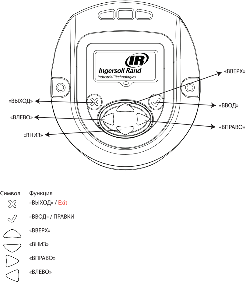
On the diagram below, the display module screen of the QX series is shown with descriptions of programmable keys.

48619652_ed2
RU-1

Overview of various menu screens
RU-2
48619852_ed2
RU
48619852_ed2
RU-\u0018
Detailed description of the display screen
On the QX series display screen, there are three sections: one MAIN section located at the top of the screen, and two ASSISTANT sections located at the lower left and right corners of the display.
Working screen
Upon pressing the ENTER button after turning on the display, this image will be displayed.
In the MAIN section, the last peak value of the torque (for the torque algorithm) or the last peak value of the angle (for the angle algorithm) is displayed together with the corresponding units of measurement.
Left Auxiliary section displays the number of cycles or the number of groups, if the number of groups is specified.
Right Auxiliary section displays the currently active configuration number.
RU-4
486198-52_ed2
Configuration
Pressing the UP button results in transitioning to the next screen.
On this screen, the CONFIGURATION setting used in the tool is displayed.
NOTE: The display module can be programmed only for Configuration 1.
Pressing the INPUT button allows transitioning to EDIT MODE (this transition procedure is the same for changing all settings).
48619852_ed2
RU-5
To change the configuration, you can use the UP or DOWN buttons. Repeated pressing of the INPUT button selects the modified configuration.
Password
The password input screen displays whether the display is locked or not. If the display is locked, the parameters of the QX series manual tools cannot be changed.
RU-6
48619852_ed2
Password can be changed after entering REPAIR MODE using the UP or DOWN buttons.
After entering the password combination 12\u00184, the user can use the left arrow button to navigate to the instrument identification meter and software version screens.
Main display - this is the Tool Location ID ["Instrument Location Identifier"].
On the auxiliary screen in the lower right corner, the display version of the display microprogram is shown.
On the auxiliary screen in the lower left corner, the display version of the motor controller microprogram is shown.
48619852_ed2
RU-\u0018
Display instrument time in HH:MM:SS format. Press the DOWN button to display instrument time in HH:MM:SS format.
Other screens are intended for special use only to view the journal location. Press the DOWN button to display the screen intended for special use only to view the journal location. Press the DOWN button again to display the second journal screen.
Press the DOWN button again to return to the tool identifier screen. Press the right arrow button to return from this screen to the password entry screen.
RU-8
48619852_ed2
Press the ENTER button to enter REPAIR MODE. Enter the correct password to unlock the instrument. Press the ENTER button to exit REPAIR MODE.
Tool parameters update for QX series
After unlocking the display by entering the correct password and pressing the "RIGHT" button, to proceed to the next settings, the configuration can be adjusted as needed.
Settings can be modified as needed using the "UP", "DOWN", "RIGHT" or "LEFT" buttons in the CONFIGURATION MODE.
48619852_ed2
RU-9
Algorithm
This screen displays the algorithm used in the configuration.
Left - torque, Right - rotation
The arrow indicates the currently selected configuration.
This value can be changed by entering the CONFIGURATION MODE using the "UP" and "DOWN" buttons.
Rotation direction
The image indicates the rotation direction of the QX series hand tools. Indicates counterclockwise rotation. Indicates clockwise rotation.
This value can be changed by entering the CONFIGURATION MODE using the "UP" and "DOWN" buttons.
RU-10
48619852_ed2
Torque units
Input — units of measurement for torque displayed in configuration 1.
Units can be changed in SETTINGS mode using the UP and DOWN buttons.
Torque
Small torque value display
Small torque value can be adjusted in this mode by entering SETTINGS mode using the UP and DOWN buttons.
Large value
Large torque value can be adjusted in this mode by entering SETTINGS mode using the UP and DOWN buttons.
48619852_ed2
RU-11
Target value
Target torque value can be adjusted in this mode by entering SETTINGS mode using the UP and DOWN buttons.
Angle
Small angle value display
Small angle value can be adjusted in this mode by entering SETTINGS mode using the UP and DOWN buttons.
Large angle value display
«HIGH VALUE» can be adjusted in this mode by entering the SETTINGS MODE using the UP and DOWN buttons.
RU-12
48619852_ed2
Torque threshold
Torque value at which the angle count starts. This value can be adjusted by entering the SETTINGS MODE using the UP and DOWN buttons.
Free speed
This screen displays the free speed of the QX series tool. This value can be adjusted by entering the SETTINGS MODE using the UP and DOWN buttons. The programmed speed is indicated as a percentage of the tool's maximum speed.
48619852_ed2
RU-1\u0018
Shift-down point configuration
This screen displays Torque Threshold for shiftdown point ["Torque threshold for shifting down to reduced speed"]. This value can be adjusted by entering the SETTINGS MODE using the UP and DOWN buttons.
Reduced speed
This screen displays the reduced speed of the QX series tool. The reduced speed can be adjusted by entering the SETTINGS MODE using the UP and DOWN buttons. The programmed speed is indicated as a percentage of the tool's maximum speed.
RU-14
48619852_ed2
Number of groups
The following screen displays the total number of bolts that should be tightened in a group, a kit, or a configuration set 1.
This number can be modified in EDIT MODE.
Radio module on/off
This screen allows the user to turn the radio module on or off. Selecting the left option disables the radio module, while selecting the right option enables it.
Save/Cancel settings
After completing the necessary changes, press the ENTER button to select the field on the left for saving settings. Press the left or right arrow button to select the field on the right for cancellation. Press the ENTER button again to exit EDIT MODE.
48619852_ed2
RU-15
2.4. Warning menu ("Warning")
The following screen appears after pressing the UP button, when the QX series instrument displays the password input screen.
2.5. Shunt calibration, RF signal level, and battery charge level
The following screen appears after pressing the UP button, when the QX series instrument displays the password input screen.
The main screen displays the shunt calibration value.
The auxiliary screen on the left displays the RF signal level, while the one on the right displays the battery charge level.
RU-16
48619852_ed2
2.6. Number of cycles
This value indicates the number of cycles performed by the QX series tool from the moment of the last replacement.
To change the value on this screen with the tool unlocked, press the "INPUT" button. Press the "UP" or "DOWN" button to reset the cycle counter. To save this change, complete a cycle before turning off the tool power. Otherwise, the cycle counter value will revert to the previous one.
2.7. Angle
Main screen - target angle
Left auxiliary screen - small angle value
Right auxiliary screen - large angle value
48619852_ed2
RU-1\u0018
2.8. Torque
Main screen - torque
Left auxiliary screen - small torque value
Right auxiliary screen - large torque value
48619852_ed2
Appendix 1. Description of status LEDs
On the display module, there are four status LEDs. Three LEDs are positioned above the display module, and one is positioned below it.
Status LEDs indicate the following.
| Red | - | Overshoot of upper limit in the last cycle of tightening. |
|---|---|---|
| Yellow | - | Last cycle of tightening ended before reaching the lower limit. |
| Green | - | Last cycle of tightening ended between upper and lower limits. |
| Blue | - | Tool is in failure state. |
Appendix 2. Tool fault codes
The following table lists error messages displayed on the Viper Tool display. All these error messages are recorded in the tool's event log:
| Code | Category | Notes | Corrective Actions |
|---|---|---|---|
| F-01 | Start malfunction: engine start mechanism | The start mechanism was required to engage when the instrument was disengaged. | It is necessary to engage the instrument using ICS, PCM, or the instrument display. |
| F-02 | Start malfunction: engine start mechanism | The start mechanism engaged during the specified delay period between cycles. | Wait for the delay period to end and press the start mechanism again. |
| F-0\18 | Start malfunction: engine start mechanism | The Smart Socket function has disabled the instrument until the PCM indicates that the appropriate adapter is connected to the instrument. | Reconnect the appropriate adapter from the selected configuration. |
| 2-xx | PM cycle count exceeded. | User configured the alarm signal generated after the instrument completes the specified number of cycles, xx = from 01 to 05. | Reset the alarm signal generation setting after completing the specified number of cycles. |
| \u0018-xx | PM time exceeded. | User configured the alarm signal generated after the specified time and date, xx = from 01 to 05. | Reset the alarm signal generation setting after the specified time and date. |
| A-10 | Connection timeout with the motor controller | The display has not communicated with the motor controller for the past 10 seconds. | Install the battery and press the start mechanism to turn on the motor controller. If the alarm signal does not turn off, it is possible that the instrument's electronic components are damaged. Contact the IR service center for repair. |
| A-55 | Display software update detected | This error appears only after updating the program firmware, if no other changes were made in the instrument's memory. | No action required. This error code is displayed only for information purposes. |
| A-AA | Display software update detected | This error appears only after updating the software and resetting the instrument configuration parameters to factory defaults. | Reload the instrument configuration parameters using ICS or the instrument display. |
48619852_ed2
RU-19
| B-01 | Failed to update controller software for the actuator. | Failed to update the controller's microprogram. | Reload the controller's microprogram via ICS. |
|---|---|---|---|
| B-50 | Wireless network error | The instrument detected instruments with the same identifier in the wireless network. | Change the instrument identifiers to ensure they do not repeat. |
| B-80 | Wireless network error | During the last 20 seconds, the instrument has lost connection with the PCM. | If PCM is unavailable, disable the wireless interface. Check the wireless network settings via ICS and ensure that the wireless network settings match the PCM. Also, verify that the instrument identifier is listed in the PCM list. |
| B-E1, B-E5, B-E9 | Wireless network error | Error code transmitted via the radio module located inside the instrument. | Check the wireless network settings via ICS and ensure that the wireless network settings match the PCM. |
| E-00 | Motor controller fault | Battery fault. | Replace the battery. |
| E-01 | Motor controller fault | Hall sensor fault: invalid state. | Hall sensor cable fault. Contact IR's service center for repair. |
| E-02 | Motor controller fault | I2T fault | Excessive current drawn over a prolonged period. Insert a 10-second delay between cycles and check if the fault has been resolved. If the connection is easily loose, try increasing the cut-off point at reduced speed so that most of the cycle is executed at high speed. |
| E-0\18 | Motor controller fault | Motor stop. | Possible electronic module damage. Contact IR's service center for repair. |
| E-04 | Motor controller fault | Motor current. | Possible electronic module damage. Contact IR's service center for repair. |
| E-05 | Motor controller fault | Overrev. | Add a delay between cycles, so that the instrument has time to cool down. |
| E-06 | Motor controller fault | Overcurrent. | Possible electronic module damage. Contact IR's service center for repair. |
| E-0\18 | Motor controller fault | Calibrate the sensor. | Faulty sensor or sensor wiring. Contact the IR service center for repair. |
| E-08 | Motor controller fault | Torque error. | Faulty sensor or sensor wiring. Contact the IR service center for repair. |
RU-20
48619852_ed2
RU
| E-09 | Motor driver controller fault | Sensor fault. | Faulty sensor or sensor wiring. Contact the IR service center for repair. |
|---|---|---|---|
| E-0A | Motor driver controller fault | Excessive step execution time. | Check if the connection is loose. For easily loosened connections, increase the step execution time parameter in the current configuration. |
| E-0B, E-15 | Motor driver controller fault | Connection timeout | Try pressing the start button again. |
| E-0C | Motor driver controller fault | Exceeded maximum torque limit. | The maximum torque limit is too low, or the connection requires excessive torque for the selected configuration settings. For heavy connections, try reducing the free rotation speed to 10% (or) reduce the torque at low speed. |
| E-0D | Motor driver controller fault | Maximum angle | Check whether the thread of the connection has come loose. The maximum angle is too large, or the connection is too loose for the given fastening parameters. |
| E-0F | Motor driver controller fault | Excessively large torque | Lower torque limit is too high, or the start mechanism was released before the cycle completion. The user must hold the start mechanism until the cycle is completed. |
| E-10 | Motor driver controller fault | Insufficient angle | Lower angle limit is too high, or the start mechanism was released before the cycle completion. The user must hold the start mechanism until the cycle is completed. |
| E-12 | Motor driver controller fault | Early start mechanism activation | The start mechanism activated before the cycle completion. |
| E-18 | Motor driver controller fault | The multi-stage cycle was not completed because the start mechanism was released too early. | The cycle execution was interrupted at one of the early stages of the main torque algorithm. Retry or check whether the connection is properly secured. |
| E-1C | Motor driver controller fault | Battery discharge error | Warning: The device may not function properly. This warning indicates that the battery is completely discharged. Replace or charge the battery. |
48619852_ed2
RU-21
| E-1E | Motor controller error | The motor controller switched to standby mode due to excessive standstill time (this error appears ONLY if the tool is connected via USB interface). | Press the start mechanism to turn on the tool. |
|---|
Parts and Service
The original language of the instruction is English. All other language versions are translations of the original instructions.
Tool repair and servicing must be carried out only by authorized service centers.
Send the document to the nearest Ingersoll Rand authorized dealer or distributor.
RU-22
48619852_ed2