

Cordless Angle Nutrunner
Product Instructions
Download the latest version of this document at http://www.desouttertools.com/info/6159929440_EN

WARNING
Read all safety warnings and instructions
Failure to follow the safety warnings and instructions may result in electric shock, fire and/or serious injury.
Save all warnings and instructions for future reference
Table of Contents
| Product Information .............................................................................................................................. | 4 |
|---|---|
| General Information......................................................................................................................... | 4 |
| Warranty............................................................................................................................... | 4 |
| Website ................................................................................................................................ | 4 |
| Information about spare parts .............................................................................................. | 4 |
| Dimensions (mm)................................................................................................................. | 4 |
| CAD files .............................................................................................................................. | 6 |
| Overview ......................................................................................................................................... | 6 |
| General overview ................................................................................................................. | 6 |
| Product description .............................................................................................................. | 7 |
| Technical data...................................................................................................................... | 7 |
| Accessories.......................................................................................................................... | 9 |
| WI-FI settings..................................................................................................................... | 10 |
| Default tool Ethernet configuration..................................................................................... | 11 |
| Installation............................................................................................................................................ | 12 |
| Installation Instructions.................................................................................................................. | 12 |
| Inserting the battery pack................................................................................................... | 12 |
| How to connect the tool to CVIMONITOR.......................................................................... | 12 |
| How to install optional accessories .................................................................................... | 12 |
| Operation.............................................................................................................................................. | 13 |
| Configuration Instructions.............................................................................................................. | 13 |
| How to configure the tool ................................................................................................... | 13 |
| How to change network parameters .................................................................................. | 16 |
| Operating Instructions ................................................................................................................... | 17 |
| How to use the tool ............................................................................................................ | 17 |
| Service.................................................................................................................................................. | 21 |
| Tool information from tool display ................................................................................................. | 21 |
| Firmware version on tool display................................................................................................... | 21 |
| Tool identification with CVIMONITOR........................................................................................... | 21 |
| Tool test with CVIMONITOR......................................................................................................... | 21 |
| Maintenance Instructions .............................................................................................................. | 21 |
| Read before maintenance.................................................................................................. | 21 |
| Instructions for transducerized tools .................................................................................. | 22 |
| Preventive Maintenance..................................................................................................... | 22 |
| Service alarm on tool display ........................................................................................................ | 22 |
| Calibration via tool display............................................................................................................. | 23 |
| Calibration with eDOCK and CVIMONITOR ................................................................................. | 23 |
| Checking before putting back into service..................................................................................... | 23 |
| Advanced tool maintenance with ACCESS KEY........................................................................... | 23 |
| Motor align ......................................................................................................................... | 24 |
| Declaring fixed accessories ............................................................................................... | 24 |
| Upgrading tool firmware..................................................................................................... Troubleshooting .................................................................................................................................. | 24 |
| 25 |
2 / 28
03/2021
What if the tool is locked ............................................................................................................... 25
List of user infos related to the tools.............................................................................................. 25
03/2021
3 / 28
Product Information
EN
Product Information
General Information
WARNING Risk of Property Damage or Severe Injury
Ensure that you read, understand and follow all instructions before operating the tool. Failure to follow all the instructions may result in electric shock, fire, property damage and/or severe bodily injury.
- Read all Safety Information delivered together with the different parts of the system.
- Read all Product Instructions for installation, operation and maintenance of the different parts of the system.
- Read all locally legislated safety regulations regarding the system and parts thereof.
- Save all Safety Information and instructions for future reference.
Warranty
- Product warranty will expire 12 months after the product is first taken into use, but will in any case expire at the latest 13 months after delivery.
- Normal wear and tear on parts is not included within the warranty.
- Normal wear and tear is that which requires a part change or other adjustment/overhaul during standard tools maintenance typical for that period (expressed in time, operation hours or otherwise).
- The product warranty relies on the correct use, maintenance, and repair of the tool and its component parts.
- Damage to parts that occurs as a result of inadequate maintenance or performed by parties other than Desoutter or their Certified Service Partners during the warranty period is not covered by the warranty.
- To avoid damage or destruction of tool parts, service the tool according to the recommended maintenance schedules and follow the correct instructions.
- Warranty repairs are only performed in Desoutter workshops or by Certified Service Partners.
Desoutter offers extended warranty and state of the art preventive maintenance through its Tool Care contracts. For further information contact your local Service representative.
For electrical motors:
- Warranty will only apply when the electric motor has not been opened.
Website
Information concerning our Products, Accessories, Spare Parts and Published Matters can be found on the Desoutter website.
Please visit: www.desouttertools.com.
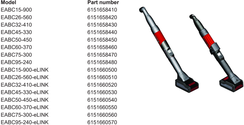
Information about spare parts
Exploded views and spare parts lists are available in Service Link at www.desouttertools.com.
Dimensions (mm)
EABC
| Model | L | ØA | ØB | ØC |
|---|---|---|---|---|
| 15-900 | 496 | 46 | 46 | 37 |
| 26-560 | 496 | 46 | 46 | 37 |
| 32-410 | 496 | 46 | 46 | 37 |
4 / 28
03/2021
EN
Product Information
| 45-330 | 506 | 46 | 46 | 37 |
|---|---|---|---|---|
| 50-450 | 546 | 46 | 46 | 37 |
| 60-370 | 559 | 46 | 58 | 41 |
| 75-300 | 582 | 46 | 58 | 49 |
| 95-240 | 582 | 46 | 58 | 49 |
| Model | D | E | F | G |
| 15-900 | 1/4" | 28 | 12 | 46 |
| 26-560 | 3/8" | 28 | 12 | 46 |
| 32-410 | 3/8" | 28 | 12 | 46 |
| 45-330 | 3/8" | 35 | 12 | 51 |
| 50-450 | 3/8" | 35 | 12 | 51 |
| 60-370 | 1/2" | 40 | 12 | 57 |
| 75-300 | 1/2" | 45 | 18 | 60 |
| 95-240 | 1/2" | 45 | 18 | 60 |
EABC e-LINK
| mm | ØC | D | E | F |
|---|---|---|---|---|
| 15-900 | 37 | 1/4" | 28 | 12 |
| 26-560 | 37 | 3/8" | 28 | 12 |
| 32-410 | 37 | 3/8" | 28 | 12 |
| 45-330 | 37 | 3/8" | 35 | 12 |
| 50-450 | 37 | 3/8" | 35 | 12 |
| 60-370 | 41 | 1/2" | 40 | 12 |
03/2021
5 / 28
EN
Product Information
| 75-300 | 49 | 45 | 18 |
|---|---|---|---|
| 95-240 | 49 | 45 | 18 |
| mm | |||
| Model | G | H | J |
| 15-900 | 46 | 66 | 59 |
| 26-560 | 46 | 66 | 59 |
| 32-410 | 46 | 66 | 59 |
| 45-330 | 51 | 66 | 59 |
| 50-450 | 51 | 66 | 59 |
| 60-370 | 57 | 66 | 59 |
| 75-300 | 60 | 66 | 59 |
| 95-240 | 60 | 66 | 59 |
CAD files
For information about the dimensions of a product, see the Dimensional drawings archive:
https://www.desouttertools.com/resource-centre
Overview
General overview
EABC tools are wireless angle-head nutrunners.
e-LINK models can be equipped with a barcode reader or a tracker.
They are hand-held by the operator and powered by a Desoutter battery pack.
On delivery, the tool display is protected by a password.
Psets and Assembly Processes can be set up with:
- Tool display
- CVI3 Vision
- CONNECT
- CVI CONFIG
Tightening reports, results and curves are collected by the system the tool is connected to.
Tool settings can be done via CVI CONFIG.
Tool maintenance can be done with eDOCK and CVIMONITOR software.
EABC tools can be used in stand-alone without communicating with systems.
The tool behaviour is then the same as an EABA tool.
The following models are equipped with eCompass feature.
- EABC 15-900
- EABC 26-560
- EABC 32-410
- EABC 45-330
- EABC 50-450
- EABC 60-370
- EABC 75-300
- EABC 95-240
- EABC 15-900-eLINK
- EABC 26-560-eLINK
- EABC 32-410-eLINK
- EABC 45-330-eLINK
- EABC 50-450-eLINK
- EABC 60-370-eLINK
- EABC 75-300-eLINK
- EABC 95-240-eLINK
6 / 28
03/2021
EN
Product Information
This feature is available for tools equipped with a gyroscope.
This feature is used to compensate any movement of the operator that might add or remove angle in the assembly. Moreover, an angle range (tool angle limits) is defined to stop the tightening if the operator movement is outside this range.
This feature is programmable with CVI CONFIG software.
To use the feature with CVI3 controller, the EPOD model (EPOD 2 Compass) must be connected to the controller. To use the feature with Connect, the feature must be activated with CVI CONFIG.
Product description
Technical data
Voltage (V)
36 V
03/2021
7 / 28
Product Information
EN
Output drive
| Model | Type |
|---|---|
| EABx 15-900 | Sq. 1/4" |
| EABx 26-560 | Sq. 3/8" |
| EABx 32-410 | Sq. 3/8" |
| EABx 45-330 | Sq. 3/8" |
| EABx 50-450 | Sq. 3/8" |
| EABx 60-370 | Sq. 1/2" |
| EABx 75-300 | Sq. 1/2" |
| EABx 95-240 | Sq. 1/2" |
EABx stands for EAB/EABA/EABC.
Torque range (Nm)
| Model | Min. / Nominal / Max. |
|---|---|
| EABx 15-900 | 5 / 13 / 15 |
| EABx 26-560 | 5 / 24 / 26 |
| EABx 32-410 | 7 / 30 / 32 |
| EABx 45-330 | 9 / 40 / 45 |
| EABx 50-450 | 9 / 45 / 50 |
| EABx 60-370 | 10 / 55 / 60 |
| EABx 75-300 | 12 / 70 / 75 |
| EABx 95-240 | 19 / 90 / 95 |
EABx stands for EAB/EABA/EABC.
Torque range (ft.lb)
| Model | Min. / Nominal / Max. |
|---|---|
| EABx 15-900 | 3.69 / 9.59 / 11.06 |
| EABx 26-560 | 3.69 / 17.70 / 19.18 |
| EABx 32-410 | 5.16 / 22.13 / 23.60 |
| EABx 45-330 | 6.64 / 29.50 / 33.19 |
| EABx 50-450 | 6.64 / 33.19 / 36.88 |
| EABx 60-370 | 7.37 / 40.57 / 44.25 |
| EABx 75-300 | 8.85 / 51.63 / 55.32 |
| EABx 95-240 | 14.01 / 66.38 / 70.07 |
EABx stands for EAB/EABA/EABC.
Rated speed (rpm)
| Model | rpm |
|---|---|
| EABx15-900 | 900 |
| EABx 26-560 | 560 |
| EABx 32-410 | 410 |
| EABx 45-330 | 330 |
| EABx 50-450 | 450 |
| EABx 60-370 | 370 |
| EABx 75-300 | 300 |
| EABx 95-240 | 240 |
8 / 28
03/2021
EN
Product Information
- EABx stands for EAB/EABA/EABC.
Weight
EABC range
| Model | Weight (kg) | Weight (lb) |
|---|---|---|
| 15-900 | 1.55 | 3.42 |
| 26-560 | 1.65 | 3.64 |
| 32-410 | 1.65 | 3.64 |
| 45-330 | 1.76 | 3.88 |
| 50-450 | 2.04 | 4.50 |
| 60-370 | 2.35 | 5.18 |
| 75-300 | 2.94 | 6.48 |
| 95-240 | 2.98 | 6.57 |
The weight is given without the battery pack.
EABC e-LINK range
| Model | Weight (kg) | Weight (lb) |
|---|---|---|
| 15-900 | 1.69 | 3.73 |
| 26-560 | 1.74 | 3.84 |
| 32-410 | .175 | 3.86 |
| 45-330 | 1.86 | 4.10 |
| 50-450 | 2.12 | 4.67 |
| 60-370 | 2.44 | 5.38 |
| 75-300 | 3.03 | 6.68 |
| 95-240 | 3.07 | 6.77 |
The weight is given without the battery pack.
Storage and use conditions
| Storage temperature Operating temperature Storage humidity Operating humidity Altitude up to Usable in Pollution degree 2 environment | -20 to +70 °C (-4 to +158 F) 0 to 45 °C (32 to 113 F) 0-95 %RH(non-condensing) 0-90 %RH(non-condensing) 2000 m(6562 feet) |
|---|
Accessories
Required accessories
| Battery pack 18 V 2.5 Ah | 6158132660 |
|---|---|
| Battery pack 36 V 2.5 Ah | 6158132670 |
| Battery pack charger | 6158132700 |
03/2021
9 / 28
Product Information
EN
| Optional accessories | |
|---|---|
| eDOCK | 6158119760 |
WI-FI settings
| Item | Desoutter default parameter | Other possible values |
|---|---|---|
| Network name (SSID) | Desoutter_1 | String of 255 characters |
| Security type | WPA/WPA2 PSK | Open Shared secret LEAP |
| Encryption type | AES/CCMP | none WEP64 WEP168 |
| Security key | mydesoutter_1 | String of 255 characters |
| Regulatory domain | Worldwide | ETSI (Europe) FCC (America) TELEC (Japan) |
| Radio band | 2.4 GHz - Channel 1-11 | 5 GHz - U-NII-1 5 GHz - U-NII-2 5 GHz - U-NII-2 ext 5 GHz - U-NII-3 |
| Data rate | 54 Mbit | 1 Mbit 2 Mbit 5.5 Mbit Mbit Mbit 11 Mbit 12 Mbit Mbit |
| 6 | ||
| 9 | ||
| 18 | ||
| 24 Mbit | ||
| 36 Mbit | ||
| 48 Mbit | ||
| 13 Mbit (MCS1) | ||
| 19.5 Mbit (MCS2) | ||
| 26 Mbit (MCS3) | ||
| 39 Mbit (MCS4) | ||
| 52 Mbit (MCS5) | ||
| 58.5 Mbit (MCS6) | ||
| Link adaptation | True | - |
| RSSI (Received Strength Signal Indication) on tool | - | > -65 dBm as a minimum |
Regulatory domain
A WLAN regulatory domain can be defined as a bounded area that is controlled by a set of laws or policies. Many countries follow standards set by FCC, ETSI, TELEC or worlwide.
2.4 GHz authorized channel list per regulatory domain
| Channel | FCC America | ETSI Europe | TELEC Japan | Worldwide |
|---|---|---|---|---|
| 1 | x | x | x | x |
| 2 | x | x | x | x |
| 3 | x | x | x | x |
| 4 | x | x | x | x |
10 / 28
03/2021
EN
Product Information
| Channel | FCC America | ETSI Europe | TELEC Japan | Worldwide |
|---|---|---|---|---|
| 5 | x | x | x | x |
| 6 | x | x | x | x |
| 7 | x | x | x | x |
| 8 | x | x | x | x |
| 9 | x | x | x | x |
| 10 | x | x | x | x |
| 11 | x | x | x | x |
| 12 | N/A | x | x | N/A |
| 13 | N/A | x | x | N/A |
5 GHz authorized channel list per regulatory domain
| Channel | Radio band | FCC North America | ETSI Europe | TELEC Japan | Worldwide |
|---|---|---|---|---|---|
| 36 | U-NII-1 | x | x | x | x |
| 40 | x | x | x | x | |
| 44 | x | x | x | x | |
| 48 | x | x | x | x | |
| 52 | U-NII-2 | x | x | x | x |
| 56 | x | x | x | x | |
| 60 | x | x | x | x | |
| 64 | x | x | x | x | |
| 100 | U-NII-2 Ext | x | x | x | x |
| 104 | x | x | x | x | |
| 108 | x | x | x | x | |
| 112 | x | x | x | x | |
| 116 | x | x | x | x | |
| 120 | N/A | x | x | N/A | |
| 124 | N/A | x | x | N/A | |
| 128 | N/A | x | x | N/A | |
| 132 | x | x | x | x | |
| 136 | x | x | x | x | |
| 140 | x | x | x | x | |
| 149 | U-NII-3 | x | x | N/A | N/A |
| 153 | x | x | N/A | N/A | |
| 157 | x | x | N/A | N/A | |
| 161 | x | x | N/A | N/A | |
| 165 | x | x | N/A | N/A |
Default tool Ethernet configuration
| Item | Desoutter default parameter | Other possible values |
|---|---|---|
| Allocation method for IP address | Static | Keep original IP address DHCP |
| IP address | 192.168. 5.221 | Refer to local settings |
| Subnet mask | 255.255.255.0 | Refer to local settings |
| Gateway | 127.0.0.1 | Refer to local settings |
| Communication port | 7477 | Refer to local settings |
03/2021
11 / 28
Installation
EN
Insert the battery pack in front or behind the tool until a locking sound can be clearly heard.
There is no ON/OFF switch: the tool is ready to operate as soon as a battery pack is mounted.
When the tool is powered on, tool LEDs are blinking. NOTICE Usage recommendations for battery packs Ensure a longer service life of the battery pack.
- Unplug the battery pack when the tool is not used.
Do not leave the battery pack on the charger when the charger power supply is off.
How to connect the tool to CVIMONITOR
Plug a battery pack to the tool.
Connect eDOCK to the tool and to the USB port of the computer.
Respect the connection order.
Launch CVIMONITOR from the computer desktop.
Click Tool in the top bar.
Click Select to select the tool.
How to install optional accessories
Refer to the user manual dedicated to the accessory available at https://www.desouttertools.com/resource-centre.
12 / 28
03/2021
EN
Operation
Operation
Configuration Instructions
How to configure the tool
Icons and buttons
The password is enabled.
The password is disabled.
Press the button "Validate/Run reverse".
Press the right button.
Press the left button.
"Validate/Run reverse" button
Right button
Left button
Validate
Save
Quit
Pset
The sound is disabled.
The sound is enabled.
The battery pack is full.
The battery pack is low.
Additional icons and buttons
| Results and curves are stored in the memory board. They are sent to the system regularly. |
|---|
| Blinking The synchronization between the tool and the system is in progress. |
| Steady The tool is connected to the system. Steady |
| The tool is not connected to the system. Check the cable between the system and the access point. Check the communication settings. |
03/2021
13 / 28
Operation
EN
How to disable the passwords
On delivery, passwords are enabled ( 1 by default ).
Pset and Maintenance passwords are used to protect settings against hazardous changes.
A red padlock is displayed on the top line of the main screen.
Press this button during 2 seconds.
Press this button to reach Configuration .
Go to Enter password , then Pset password , use the buttons to display "1", save and and validate. The red padlock turns green.
The procedure is the same to disable the Maintenance password.
How to set up new passwords
To set new passwords, current passwords must be disabled and the green padlock displayed.
Go to the main screen.
Press this button during 2 seconds.
Press this button to reach Configuration .
Go to Set password , then Pset password , use the buttons to enter a figure from 0 to 999, save and validate.
- Setting the password to 0 will disable all password protections.
The procedure is the same to set up a new Maintenance password.
Sound, torque unit
Sound
The tool can emit sounds to alert the operator in case of problems or events that may happen during the tightening operation.
Sounds can be set for the following topics:
- tightening out of tolerances
- calibration procedure
- preventive maintenance
- low battery
- hardware failure
- maintenance
- On tool delivery, the sound is disabled.
Go to CVI CONFIG to enable the feature.
Click this icon to update the product.
Torque unit
The following torque units are available:
14 / 28
03/2021
EN
Operation
- Nm
- ft.lb
- in.lb
- kg.m
- kg.cm
- oz.in
- dNm
On tool delivery, the torque unit is set to "Nm" by default.
Go to CVI CONFIG to change the torque unit.
Click this icon to update the product.
How to set up the reverse mode
On tool delivery, the "Reverse" function is disabled. Go to CVI CONFIG to set up reverse settings.
How to visualize network parameters
Go to the tool display.
Press this button during 2 seconds.
Press this button to reach Maintenance / Network .
How to set up the tool in stand-alone working mode
Changing the tool working mode will erase the Pset, the results and curves present in the tool memory.
Launch CVIMONITOR.
Click this icon.
Click Tool working mode .
03/2021
15 / 28
Operation
EN
Tick Standalone .
Click Write to tool .
Click File > Exit to quit.
How to set up parameters
Plug the eDOCK to the tool and connect it to the USB port of the computer where CVI CONFIG is installed.
Launch CVI CONFIG.
Go to the tree view area.
Create or select a "Factory / Assembly Line / Working area".
Right-click the "Working area" and add a product.
Select ExBC Standalone .
Refer to CVI CONFIG Configuration manual available at https://www.desouttertools.com/resource-centre.
Instructions for use
The tool behaviour is the same as an EABA or EPBA tool.
6 Psets are available.
Refer to the Product Instructions of the tool available at https://www.desouttertools.com/resource-centre.
How to change network parameters
Via CVIMONITOR and eDOCK
Refer to chapter How to connect the tool to CVIMONITOR [Page 12] .
Click this icon.
Click this icon to display the current parameters of the tool.
Change the parameters.
Refer to chapters Default tool Ethernet configuration [Page 11] and WI-FI settings [Page 10] .
16 / 28
03/2021
EN
Operation
- Check that IP address, subnet mask and port number of the controller/hub are compatible.
Click this icon to write the new parameters into the tool.
Via Easy Pairing
When the pairing is done to CONNECT via RFID, WI-FI settings are directly written to the tool.
- Network settings must have been done previously by using CVI CONFIG.
How to set up Psets and Assembly Processes
On delivery, the tool has no tightening process.
Launch CVI CONFIG software to create Psets and Assembly Processes and transfer the configuration to the tool.
- A simple Pset can also be created from the display of the system the tool is connected to.
Refer to the user manual of CVI CONFIG available at https://www.desouttertools.com/resource-centre.
P0 is displayed on the tool screen and the tool is locked.
A Pset is shown by this icon.
A Pset is a tightening operation combining one or several steps, each step describing a function.
The tool will execute the steps one after the other in the given order.
Content of the steps and the order can be changed at any time.
- The minimum to run the tool is 1 Pset containing 1 step.
An Assembly Process is commonly called AP and is shown by this icon.
The Assembly Process available in products and systems consists in executing a Pset a certain number of times or unlimited. This feature is named Batch .
Create as many Psets / Assembly Processes as you want.
For each of them, enter a description which will be displayed on the tool screen.
Transfer the configuration to the tool.
- If the transfer fails, unplug and plug the battery pack. Re-start the transfer.
Operating Instructions
How to use the tool
How to select the Pset to run
Go to CVI CONFIG and check that "Default Pset selection source" in the configuration of the Tightening Unit is set to "Tool display".
From the tool main screen, press the right button briefly. The current Pset is displayed.
Press OK. The Pset number turns orange.
Use the left or right button to scroll through the list.
Press OK to select the displayed Pset. The Pset is now in blue.
Once the Pset is selected and the tool is ready, the Pset number turns green.
Press the trigger to start the process.
- When out of tolerances, a sound can be heard (if configured).
See below some examples of the Pset status on the tool display.
03/2021
17 / 28
Operation
EN
| Icon status | Description |
|---|---|
| Pset 2 is the next Pset to run. The tool is ready to start. | |
| There is no Pset selected. The tool is locked. Select a Pset. Pset 4 is selected. The tool is locked. | |
| The tool may be expecting an external order. |
How to select the Assembly Process to run
Go to CVI CONFIG.
Check that:
"Running mode" in the configuration of the Tightening Unit is set to "Assembly Process".
Start condition of the Assembly Process is set to "Tool display".
From the tool main screen, press and hold the right button.
Press OK. The Assembly Process number turns orange.
Use the left or right button to scroll the list.
Press OK to select the displayed Assembly Process. The number is now in blue.
Once the Assembly Process is selected and the tool ready, the Pset number turns green.
Press the trigger to start the process.
Starting the tool
Fit the tool with a suitable socket.
Select the appropriate Pset.
Hold the tool by means of the handle and apply to the fastener to be tightened.
WARNING Risk Of Injury
As the reaction force increases in proportion to the tightening torque, there is a risk of severe bodily injury of the operator as a result of unexpected behavior of the tool.
- Make sure that the tool is in perfect working order and the system is programmed correctly.
Press the trigger to start the tool.
Tightening status and LED reporting
Reporting LEDs
| 1 | Red |
|---|---|
| 2 | Green |
| 3 | Yellow |
How to read the tightening report
| LED color | Description | Action to do |
|---|---|---|
| Green | Accept report | None |
18 / 28
03/2021
EN
Operation
| LED color | Description | Action to do |
|---|---|---|
| Yellow | Incomplete rundown | Tighten again. |
| Yellow and red (orange) | Reject report | Loosen and tighten again. |
| Red | Above max. limits | Remove and replace the fastener. |
How to have the batch count on the tool display
Go to the system/tightening unit/tool settings.
Go to the tightening unit.
Check that "Batch count" or "Ellipse" is ticked in the menu "Display parameters".
When the process is done, results are displayed.
Torque and angle values
Batch count
Ellipse
The ellipse represents the batches. In this example, 3 tightenings out of 4 are completed.
How to interact on the Assembly Process
Press the left button to abort the Assembly Process.
The following actions are protected by the "Maintenance" password. To have them available, enter the Maintenance password in the "Configuration" menu.
During the Assembly Process, press the left button to activate the actions.
How to reverse the rotation
03/2021
19 / 28
Operation
EN
1 Run reverse button
Press this button.
Red and green LEDs are blinking alternatively.
Apply the tool to the fastener and press the trigger.
How to smooth the tool stop
The "Ergostop" function must be disabled for tightening tests or certification on tightening benches.
Ergostop allows a smoother tool stop to reduce the torque reaction on the operator.
On tool delivery, this feature is disabled.
Go to CVI CONFIG to enable the feature.
How to wake up the tool
The tool display switches off automatically after 2 minutes of inactivity.
Press the trigger.
The WI-FI is de-activated after 5 minutes of inactivity.
Refer to "Power saving mode" configurable in CVI CONFIG.
Press the trigger.
The tool powers off after 30 minutes of inactivity.
Long press the reverse button.
Refer to "Power off" configurable on tool display or with CVI CONFIG.
Unplug and plug the battery pack.
20 / 28
03/2021
EN
Service
Service
Tool information from tool display
Go to "Maintenance/Tool" menu to get the following information:
| Total counter | Number of tightenings since the manufacturing of the tool. The current voltage value is displayed. |
|---|---|
| Battery | The "Low battery" message is displayed when lower than 32 V. At 31 V, the tool stops. |
| Serial number | 18B64685 for example. |
Firmware version on tool display
The firmware version of the tool is displayed in the menu "Maintenance/Tool". CX.YY.ZZ.
Tool identification with CVIMONITOR
Click this icon.
Click Tool identification .
Go to the bottom of the screen and click Read tool.
A green tick indicates the reading is successful.
Tool test with CVIMONITOR
Click this icon.
Click Tool test .
Click Start tool test .
LEDs start blinking.
Press the triggers, the reverse button.
Click Start audio test .
The tool emits a sound.
- The green tick displayed indicates the function is working properly.
Maintenance Instructions
Read before maintenance
WARNING Connection Hazard
The tool can start unexpectedly and cause severe bodily injury.
- Prior to any maintenance task, disconnect the tool.
Maintenance should be performed by qualified personnel only .
Follow standard engineering practices and refer to exploded views for disassembling and reassembling the different parts of the system.
Take into account the following instructions given in the exploded views.
Be cautious: when reassembling, tighten the right direction.
Left hand thread
03/2021
21 / 28
Service
EN
Right hand thread
When reassembling:
Apply the recommended glue.
Tighten to the required torque.
Lubricate with the required grease or oil. Do not apply too much grease on gears or bearings; a thin coat shall be sufficient.
Instructions for transducerized tools
- Do not damage the wires when pulling out the connectors.
- Do not pull out the torque transducer wires.
- Ensure that wires are not crushed.
Preventive Maintenance
Recommendations
Overhaul and preventive maintenance are recommended at regular intervals once per year or after a maximum number of tightenings (refer to the table below) depending on which occurs sooner.
Maintenance frequency
500,000 tightenings
Service alarm on tool display
An alarm can be displayed when service is required.
This icon is displayed.
One of the service levels is displayed (see below). When no service is required, "none" is displayed. A sound is heard.
It is possible to set 3 service levels:
| Level | Number of tightenings | Service level |
|---|---|---|
| 1 | 25 000 | Calibration |
| 2 | 250 000 | Intermediate (for heavy duty applications only) |
| 3 | 500 000 | Standard |
Go to the main screen.
Press this button during 2 seconds.
Press this button to reach Maintenance .
Go to Tool , then Service alarm , select a level, save and validate.
Once the service is performed, reset the indicators.
Go to the "Maintenance/Service alarm" menu and press OK.
22 / 28
03/2021
EN
Service
Calibration via tool display
The calibration procedure is recommended to compensate for any possible drift of the tool torque or after each change of tool element.
This function is set in the "Maintenance" menu.
- Enter the Maintenance password in the "Configuration" menu.
- Insert a torque transducer in line with the tool and connect it to any measuring unit from the Desoutter range.
- Go to "Maintenance/Calibration". Select the number of tightenings required to execute the calibration and press OK. Run a Pset the number of times already configured (at max. torque and with an angle above 180° (at low
- speed)).
- Go on with other tightenings by pressing the trigger.
- The average torque value is displayed in white. On the line below, enter the average torque value measured by the measuring unit (± 20 % vs the tool nominal torque are allowed).
- Use the left/right buttons to increase or decrease the value.
Press OK and save your data.
Calibration with eDOCK and CVIMONITOR
The calibration procedure is recommended to compensate for any possible drift of the tool torque or after any change of tool element.
In the manual mode, the standard procedure is executed. Measurements and values are typed manually by the operator.
The equipment required is as follows:
- Tool equipped with a torque transducer in line
- CVIMONITOR
- Delta measuring unit
Click this icon.
Click Tool calibration .
The standard procedure is as follows:
- Select the Pset to execute.
- 2.
- Select the number of tightenings to perform (5 by default, 50 as a maximum).
- According to the test bench use, the tightening may be preceeded by a loosening.
- Click "Start calibration".
- Start performing the first loosening / tightening operation. The operation must be successful.
- At the end of each operation, enter the torque value on the measuring unit.
- When all operations are performed, a new calibration value is displayed.
Checking before putting back into service
Prior to putting the equipment back into service, check that its main settings have not been modified and that the safety devices work properly.
Advanced tool maintenance with ACCESS KEY
Launch CVIMONITOR.
To activate the screens, you need to have an ACCESS KEY USB stick with the right profile (configured with the Desoutter CVIKEY software).
If not, contact your CVIKEY manager for support.
03/2021
23 / 28
Service
EN
Motor align
Click this icon.
Click Motor align .
It is mandatory to calibrate the tools after a motor align.
It is recommended to align the motor in case of motor, transducer or PCB change.
Before starting, press the trigger and KEEP IT PRESSED DURING THE COMPLETE PROCESS . If not, the tool could be severely damaged.
While pressing the trigger, click Start motor align .
The process will run during around 1 minute and will stop automatically.
Click "Stop motor align" to stop the process before the end.
Release the trigger.
Declaring fixed accessories
A fixed accessory mounted on a tool must be declared in this screen.
Click this icon.
Click Tool identification .
Select the type of accessory and fill in the parameters.
Click Write to tool .
It is mandatory to calibrate the tool equipped with the fixed accessory before use.
Upgrading tool firmware
Click this icon.
Click Upgrade tool firmware .
Contact your Desoutter representative to get the last firmware version.
Follow the instructions on screen.
24 / 28
03/2021
EN
Troubleshooting
Troubleshooting
What if the tool is locked
| Description | Solution |
|---|---|
| There is no communication with the sys- tem | Check WI-FI parameters, IP addresses and communication port in the system, tool and WI-FI access point. |
| The message "Tool locked" is displayed. | Check the settings of the tightening pro- cesses (Pset and Assembly Process). |
| The message "Tool error" is displayed. | Press the trigger to get more informa- tion. |
| The display remains black. None of the LEDs are turned on. The tool is not able to start. | Try first to wake up the tool. Replace the battery pack. |
Contact your Desoutter representative to get more information and support.
List of user infos related to the tools
| Number | Description | Procedure |
|---|---|---|
| I004 | Span failure | 1- Span value from torque sensor is outside bounds. 2- Try once again to start the tool with no mechanical constraints. If the problem occurs again, contact your Desoutter representative for support. |
| I005 | Offset failure | 1- Offset value from torque sensor is outside bounds. 2- Try once again to start the tool with no mechanical constraints. If the problem occurs again, contact your Desoutter representative for support. |
| I026 | Tool maintenance alarm n1 | 1- The tool tightening counter has been reached. |
| I027 | Tool maintenance alarm n2 | 1- The tool tightening counter has been reached. |
| I038 | Tool logs | 1- Unexpected tool software exception. 2- Log file has been generated by the tool. 3- Contact your Desoutter representative for support. |
| I046 | Abnormal battery current | 1- Abnormal battery current consumption. Check the Pset settings. 2- This error can be due to wrong speed settings. |
| I063 | Battery pack removed | 1- Battery pack removed from the tool detected. 2- After few seconds, the tool will shutdown |
| I065 | External start ignored | 1- External start detected but ignored. 2- Check tool and external start configuration. |
| I103 | Invalid rotary selector direction | 1- Change the direction of the rotary selector. 2- Verify that the rotary selector is in correct position or not damaged. |
| I205 | Torque settings | 1- Invalid Torque setting: torque is greater than tool characteristics. 2- Check Pset settings with the tool characteristics. |
| I206 | Speed settings | 1- Invalid speed setting: speed is greater than tool characteristics. 2- Check Pset settings with the tool maximum speed. |
03/2021
25 / 28
Troubleshooting
EN
| Number | Description | Procedure |
|---|---|---|
| I210 | Invalid Pset selected | 1- The selected Pset does not match the Pset selectable in the Assembly Process. |
| I211 | Invalid trigger configuration | 1- The tool connected to the system is not equipped with the trigger required by the trigger configuration. 2- Adjust your trigger configuration to the tool or change the tool according to the trigger configuration. |
| I224 | IGBT too hot | 1- Power electronics too warm. 2- Let the system cool down. |
| I251 | No Pset selected | 1- No Pset selected. 2- Select a Pset. |
| I270 | Time settings | 1-Invalid Time setting|2-Check Pset settings with cor- rect time value settings |
| W010 | Tool calibration expired | 1- The tool calibration date has expired. 2- A tool calibration needs to be done to ensure the measurement accuracy. |
| W028 | Battery tool version error | 1 - Battery tool version and system version are not compatible. |
| W030 | The battery is low. | 1- The battery is low. 2- Recharge the battery. |
| W033 | Tool time error | 1- The tool time is not set correctly. The tightening re- sults will not be time stamped. |
| W036 | Tool memory full | 1- The tool memory is full. 2- Connect the tool to the system to empty the mem- ory. |
| W062 | Overload of torque | 1- Overload of the torque (could be a rehit). 2- Check the tool cable is not damaged. |
| W212 | Result not stored | 1- It is not possible to store the tightening result in the system. 2- Contact your Desoutter representative for support. |
| W216 | Current high | 1- Maximum current exceeded. 2- Contact your Desoutter representative for support. |
| W267 | Result transfer error | Result transfer error. |
| E007 | Motor too hot | 1- Tool is locked because the maximum motor temper- ature has been reached. 2- Tool will remain locked until the motor temperature comes back to its normal value. |
| E008 | Tool angle fault | 1- Problem detected with the tool angle sensor. 2- The tool needs maintenance. |
| E009 | Tool invalid parameters | 1- Check the tool compatiblity. 2- The tool memory cannot be read or is invalid. 3- The tool needs maintenance. If the problem occurs again, contact your Desoutter representative for sup- port. |
| E012 | Tool EEPROM error | 1- The tool memory cannot be read or is invalid. 2- The tool needs maintenance. If the problem occurs again, contact your Desoutter representative for sup- port. |
| E018 | Torque out of range ! | 1- The target torque value is above the tool maximum torque. 2- Check Pset settings with tool characteristics. |
| E029 | The battery is empty. | 1- The battery back is discharged. The tool cannot tighten. 2- Recharge the battery pack. |
| E031 | Battery error | 1- Abnormal battery voltage. The tool cannot tighten. 2- Recharge the battery pack. If the problem occurs again, replace the battery pack. |
26 / 28
03/2021
EN
Troubleshooting
| Number | Description | Procedure |
|---|---|---|
| E032 | Tool display error | 1- Board display malfunction. 2- Contact your Desoutter representative for support. |
| E034 | Tool memory error | 1- The tool memory does not work properly. 2- Contact your Desoutter representative for support. |
| E035 | Tool memory locked | 1- The tool memory is locked to protect old data from rewriting. 2- Connect the tool to the computer via eDOCK to re- trieve old data. |
| E037 | Tool trigger error | 1- The tool trigger does not work properly. 2- Check and clean the trigger. If the problem occurs again, contact your Desoutter representative for sup- port. |
| E045 | Abnormal battery voltage | 1- Check the battery pack. 2- This error can be due to charger malfunction or end of life battery. |
| E047 | Battery is too low. | 1- Check the battery pack. 2- If the problem occurs again, replace the battery pack. |
| E048 | Battery type not allowed | 1- Battery type not allowed. 2- Replace the battery pack or your configuration. |
| E223 | Drive init error | 1- Software failure. 2- Restart the system. 3- If the problem occurs again, contact your Desoutter representative for support. |
| E227 | Motor stalled | 1- Motor stalled (could be missing phase, wrong motor tune or power electronics failure) 2- Try once again. 3- If the problem occurs again, contact your Desoutter representative for support. |
| E228 | Drive error | 1- Software failure. 2- Restart the system. 3- If the problem occurs again, contact your Desoutter representative for support. |
03/2021
27 / 28
More Than Productivity